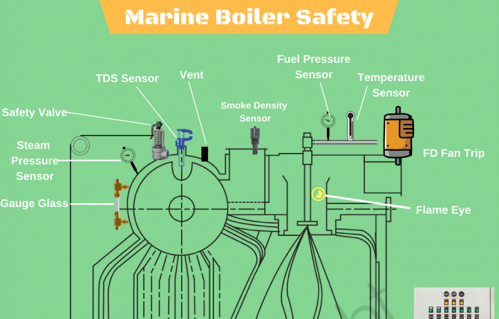
Marine boilers auxiliaries include the boiler control system, forced draught fans, de-superheater, fuel oil pumps, heaters and filters, exhaust gas air and feedwater heaters. Fixtures and fittings consist of steam safety valves, feed control valves level glasses, sootblowers and blowdown valves.
There are many different types of marine boilers, however, they have all got one thing in common their auxiliary components, and their fixtures and fittings. These form an equally important function as the boiler just wouldn’t operate efficiently without any one of them.
This article follows on from ‘Marine Boilers’ and I have written it in a similar manner; listing the different types of boilers auxiliaries with their function and location and shown in an accompanying sketch.
Please refer to the sketch as required
Combustion Air system
1. Forced Draught Fans
These are centrifugal fans and supply combustion air under pressure to the furnace, via the air heater.
2. Combustion Air Heater
This is a heat exchanger placed in the path of the exiting furnace exhaust gasses it is normally rectangular having horizontal banks of tubes over which the hot gasses pass. This heat is transferred to the air passing through the tubes increasing its temperature and, the efficiency of combustion in the furnace.
3. Furnace Air Register
This is a circular ducting which into which the burner is fitted. It is fixed to the furnace front and supplied with the combustion air from the fans. It has dampers and diverting plates fitted internally, to effectively swirl the heated air into the furnace combustion chamber along with the oil from the burner.
Feedwater System
4. Economiser
This is another heat exchanger which makes use of the hot boiler furnace exhaust gasses as they head up the flue. The economiser has a bank of tubes through which the feedwater is pumped under very high pressure by the boiler water feed water. The hot gasses pass on the outside of the tubes and a soot-blower may be fitted to blow the accumulation of soot from the tubes. A disadvantage is that condensation of the flue gasses can lead to acid eroding tubes and casing, the correct choice of materials for these components is imperative i.e. stainless steel used.
5. Main Feed Water Check Valve
This is a screw-down non return valve and is fitted to the feedwater inlet pipe to the boiler, normally being full open. A wee aside to this; I was a young lad sitting part A of my Second’s Tickets in the Board of Trade Office in Belfast in the late sixties. I had got about half way through the drawing paper which was- yes a boiler check valve, when I discovered to my horror that I had chosen a wrong scale and was about to run off the paper. Just then a loud alarm sounded, everybody was evacuated to a safe area outside as there was a bomb alert in the building.
Great I thought, we will have to start over again when we get back in and this time I will get the scale right! Alas; it was a false alarm and we were back inside in ten minutes, being instructed to carry on where we left off. Needless to say I had to resit the drawing part of my tickets!
Anyway the check valve acts as an isolating valve if working on the feedwater line with furnace shutdown. Non-return or no – always shut it tight!
6. Feedwater Control Valve
This is an automatic valve situated between the economiser and the main check valve. It controls the level of water in the boiler, opening and closing as required.
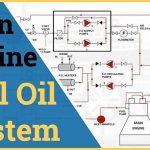
Fuel Oil System
7. Fuel oil Pump
The fuel oil pump extracts the heavy fuel oil from the fuel oil bunker tank. This tank usually has steam heating coils inside it to heat the oil and raise its viscosity for pumping. The pump discharges the oil to the furnace burners through a system of filters and heaters.
8. Fuel oil strainers, suction and discharge filters.
The strainers are placed before the suction filter and remove any large globules of oil. There is a set of duplex filters before and after the fuel oil pump. These can be easily taken of line for the required frequent cleaning.
9. Fuel oil Heater
From the pump the oil passes through the discharge filter and on to fuel oil heater, usually a vessel with coils through which the steam passes and heats the oil to atomising temperature. From the heater the oil is pumped under pressure to the burner.
10. Fuel oil Burner
The oil is now at the correct temperature and pressure for efficient atomisation which takes place at the end of the fuel oil burner, inside the furnace. The oil burner is normally located at the centre of the combustion air register so that atomisation takes place with the introduction of the combustion air ensuring a good air/fuel ratio.
Steam System
11. Steam Superheater
The steam passes from the top of the steam drum, back into the boiler where it passes through a superheater. The superheater is normally slung from the boiler drum, between the banks of water tubes and in the path of the furnace exhaust gasses. The gasses heat the steam passing through the superheater removing any moisture and increasing its temperature and pressure, imperative to the supply to the main turbine
12. De-superheater
As the main turbine requires superheated steam, most auxiliary turbines require de-superheated steam e.g. main power generators, boiler feed pumps, and cargo pumps on oil tankers. Desuperheated steam is produced by spraying hot water through single or multiple sprays into the superheated steam, either in a pressure vessel or in a section of sleeved pipe. De-superheated steam can also used at reduced pressure for bunker heating, fuel oil heating, accommodation heating, deck and galley steam.
Sootblowers
13. Sootblowers
The use of cheap heavy fuel oil to fire the boilers along with incorrect air/fuel ratios during maneuvering inevitably leads to the outside of the water tubes becoming laden with soot. To remove the soot, regular cleaning is required and this is executed by the use of a sootblower. These consist of long perforated pipes, spanning the length of the tube bundles and located between them at spaced intervals. The pipes are rotated by a motor and as they rotate and either steam, superheated steam, or compressed air is discharged through the nozzles blowing the soot from the pipes. The air heater and economiser can also have sootblowers.
Safety Valves
14. Steam drum safety valves
These fitted to the steam drum outlet header, the Board of Trade stipulating the fitting of two safety valves, should one fail to lift.
15. Superheater safety valve
There is normally only one superheater safety valve, situated on the main engine steam supply outlet header.
The superheater safety valves should always be set to lift before the main drum safety valves, this prevents the superheater coils from becoming damaged due to lack of steam flow. (We were always told that If the drum valve lifted first, the steam would disappear up the flue rather than go through the superheater – Comments?)
Boiler Automatic Control Panel
Bailey Control Board
Most of the above boiler auxiliaries are controlled by the Bailey board, an invention by an American called E.G. Bailey in 1916.
The board controls the air/fuel input, boiler feed water supply, steam flow temperature and pressures. It also records all this activity over a twenty-four hour period on circular chart recorders.
The boiler is usually controlled manually when on standby entering and leaving port.