Modern methods available for ship resistance evaluation are based on CFD (Computational Fluid Dynamics). However, there are four basic methods including CFD that are used commonly in the industry.
The choice of the method depends not only on the capability available but also on the accuracy desired, funds available and degree to which the approach has been developed.
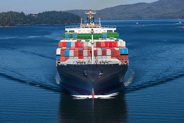
Image for Representation purpose only
Following diagrams gives an idea about the various evaluation techniques used for measuring ship resistance.

In this article we shall be discussing about the traditional method, regression based method & model test method.
Traditional and standard series analysis method
Traditional and standard series analysis comprises of methods that are based on experiments conducted by various scientists. It is more of a theoretical approach than practical, based on graphs and observations by notable scientists in the field of naval architecture.
Taylor’s method
Admiral Taylor in 1910 published the results of model tests on a series of hull forms. His work has been extended to embrace a range of Froude number from 0.3 to 2.0. The series comprised of 80 models in which the results are published for draft ratios of 2.25, 3 and 3.75 with five displacement length ratios. Eight prismatic coefficients were used spanning the range 0.48 to 0.8, which tends to make the series useful for faster and less full vessels. The procedure is centered on the calculation of the residual resistance coefficients based on the data for each B/T value corresponding to the prismatic and Froude number values of interest. The residual resistance component CR is found by interpolation from the three B/T values corresponding to the point of interest. The frictional resistance component is calculated on the basis of Reynolds number and wetted surface area together with a hull roughness allowance.
The result of this calculation is added to the interpolated residuary resistance coefficient to form the total resistance coefficient CT from which the naked effective Horsepower is derived for each of the chosen Froude number values from the relation –
EHP = ACT (VS) ^3, ‘A’ is the Wetted Surface Area.
Ayre’s method
This method was based on model test data, using a series of hull forms relating to colliers the method centers on the calculation of a constant coefficient C2 which is defined by the equation –
EHP = ACT (VS) ^3, ‘A’ is the Wetted Surface Area.
This relationship implies that in the case of full-sized vessels of identical forms and proportions, the EHP at corresponding speeds varies as the numerator and that the denominator is a constant at given values of Froude number. The value of the denominator is estimated for a standard block coefficient. Corrections are then made to adjust the standard block coefficient to the actual value and corrections are applied to cater for variations in the beam–draught ratio, position of the LCB and variations in length from the standard value used in the method’s derivation.
Standard series data
In addition to the more formalized methods of analysis there is a great wealth of data available to the ship designers and analyst in the form of model data and more particularly in model data relating to standard series hull forms. That is, those in which the geometric hull form variables have been varied in a systematic way. Unfortunately, there is little uniformity of presentation in the work as the results have been derived over a long period of time in many countries of the world. The designer therefore has to accept this state of affairs and account for this in his calculations. In addition, hull form design has progressed considerably in recent years and little of these changes is reflected in the data cited in these references. Therefore, unless extreme care is exercised in the application of such data, significant errors can be introduced into the resistance estimation procedure.
In more recent times the Propulsion Committee of the ITTC have been conducting a cooperative experimental programme between tanks around the world. The data so far reported relates to the Wigley parabolic hull and the Series 60, Cb = 0.60 hull forms.
Regression – based method
Ship resistance prediction based on statistical regression methods has been a subject of some interest for a number of years. The theme of statistical prediction was then taken up by Holtrop in a series of papers. The papers written by him trace the development of a power prediction method based on the regression analysis of random model and full – scale data together.
Modern day regression data is based on the following ship resistance equation:
RT = RF(1+k1) + RAPP + RW + RB + RTR + RA
In this equation the frictional resistance RF is calculated according to the 1957 ITTC friction formulation, and the hull form factor ‘(1+k1)’ is based on a regression equation and is expressed as a function of after-body form, breadth, draught, length along the waterline, length of run, displacement and prismatic coefficient.
The appendage resistance is calculated according to the Holtrop approach, in which the frictional coefficient CF again determined by the ITTC 1957 line.
Similarly, if a bow thruster is fitted their influence should be taken into account by the term RBT.
The prediction of the wave making component of resistance has proved difficult and in the last version of Holtrop’s method a three-banded approach is proposed to overcome the difficulty of finding a general regression formula. The ranges proposed are based on the Froude number, they are as follows:
Range 1: Froude number > 0.55
Range 2: Froude number < 0.4
Range 3: 0.4 < Froude number < 0.55
The Holtrop method provides a most useful estimation tool for the designer. However, like many analysis procedures it relies to a very large extent on traditional naval architectural parameters. As these parameters cannot fully act as a basis for representing the hull curvature and its effect on the flow around the vessel there is a natural limitation on the accuracy of the approach without using more complex hull definition parameters. At the present time considerable research is proceeding in this direction to extend the viability of the resistance prediction method.
Direct model tests
Model testing of a ship in the design stage is an important part of the design process and one that, in a great many instances, is either not explored fully or is not undertaken.
While carrying out the resistance test, the ship model is towed by the carriage and the total longitudinal force acting on the model is measured for various speeds. The breadth and depth of the towing tank essentially governs the size of the model that can be used. The model, constructed from paraffin wax, wood or glass-reinforced plastic, requires to be manufactured to a high degree of finish and turbulence simulators placed at the bow of the model in order to stimulate the transition from a laminar into a turbulent boundary layer over the hull. The model is positioned under the carriage and towed in such a way that it is free to heave and pitch, and ballasted to the required draught and trim.
There are basically two types of resistance tests: the naked hull and the appended resistance test.
In order to prevent uncontrolled laminar flow the propeller should be replaced by a stream-lined cone. This prevents flow separation in the area. The resistance extrapolation process follows Froude’s hypothesis and the similarity law is followed. As such the scaling of the residual, or wave making component, follows the similarity law.
The rest is then followed as per the equations provided in the regression technique. The model is run throughout the length of the tank at particular intervals and the values of ship resistance is noted with the help of the dynamometer fitted within the ship.

The above given techniques have surely helped in the evaluation of resistance calculation over the decades, however, in the present situation this tiresome technique of regression or model based has been replaced by software’s like CFD, in which you have to feed the data and the software provides you with the detailed analysis.


Comments are closed