In the last fifty years, there has been a rise in the necessity for marine vehicles that are capable of providing performances higher than typical commercial ships. High performance, here, implies high speed. This required intense technical studies because it was not possible to achieve these high speeds with conventional propulsion systems, which otherwise, would have made it uneconomic, owing to the tremendously high power requirements.
Hence, newer propulsion systems and hulls were designed based on experiments carried out in model basins. This gave rise to some ways, in which, high performance could be achieved by these small crafts with special hull designs. This article discusses some of the most widely used technologies in the field of high-performance marine vehicles.
Planing Crafts:
Have you ever noticed the phenomenon of a stone skipping on the surface of the water? That occurs due to the planning effect, which was first explained by surging a flat plank along the water surface at a certain angle of attack, as shown below.

Figure 1: Planing action.
When a flat plank is slid along the water surface at a particular angle of attack, a stagnation point is formed under the plank. This is the point where the velocity lines of the fluid are perpendicular to the plank, creating a standard reaction as shown. There are two components of this typical reaction. The component in the perpendicular direction tends to lift the plank from the water surface and is called the Lift. The horizontal component is the drag, resisting the motion of the plank. This stagnation point also creates the spray.
Now, it is due to the lift force, that the plank raises above the water surface. The lift reduces to zero when the plank loses contact with the water surface. It would lift from the surface till gravity results in it coming down back onto the surface, thus repeating the same process in a cycle. What is to be noted here is, the lift force is a function of the forward velocity of the plank and the angle of attack. An optimum angle of attack would provide the maximum lift force.
This phenomenon of a planning body being lifted from the water surface is called the porpoising action, and this is why the stone you threw skipped along the surface of the water. It was this principle that was applied in the design of the hulls of planning crafts.

Figure 2: Planing craft.
The above image shows a planning craft in action. One of the most important conditions that are to be met by planning crafts to provide optimum performance is the trim angle, which in turn provides the lift force. Chines are a notable feature in most of the planning hulls because they help in directing the spray away from the hull, as shown in the figure below. Some hulls feature double and triple chines designed for those that generate more spray.

Figure 3: Single chine hull cross section.
But why is there a need to direct the spray away from the hull? This introduces us to a new term called spray resistance. When the spray travels aftward, it wets the hull, which results in an added drag called the spray drag, and this contributes to almost 10 to 15 percent of the total drag in planning crafts. It is, therefore, a prime focus of the designer of a planning craft hull to minimise the spray resistance as much as possible.
Another way of conceptualising the spray resistance is to realise that it is the energy spent by the craft in generating the spray. Since the spray is produced due to the forward motion of the craft, which is in turn powered by the craft’s propulsion system, spray resistance forms a component of the power used up to overcome the total drag of the craft.
At low speeds planning crafts are less stiff in roll motions, however, the stiffness of roll increases at higher speeds, which means a planning craft cruising at a higher speed in beam seas would be more prone to higher degrees of the roll than at lower speeds. The angle made by the hull to the horizontal, at the keel is called the angle of deadrise. To combat the above effect, the deadrise is kept to a minimum.
SWATH (Small Waterplane Area Twin Hull):
Since catamarans (double hulls) have higher transverse stability than monohulls, it sometimes comes across as a problem. Increased transverse stability means reduced seakeeping abilities. In order to combat this in double hulls, SWATHs have been developed to feature low waterplane area. These are also displacement type hulls like typical displacement catamarans, and the lost hull volume due to low waterplane is compensated by providing increased cross sections in the part of the hull that is further from the water surface, as shown in the figure below. Each such cylindrical section is commonly called a pod.

Figure 4: Difference between a displacement catamaran and SWATH.
The small waterplane significantly reduces the wave drag at higher speed and increases seakeeping abilities of the hull. But it also comes with a con. The small waterplane area results in increased sensibility to load changes within the hull. This is compensated by a compensating system that uses ballast water to make up for the load changes to prevent unwanted trim and heel conditions.

Figure 5: SWATH with twin pods.
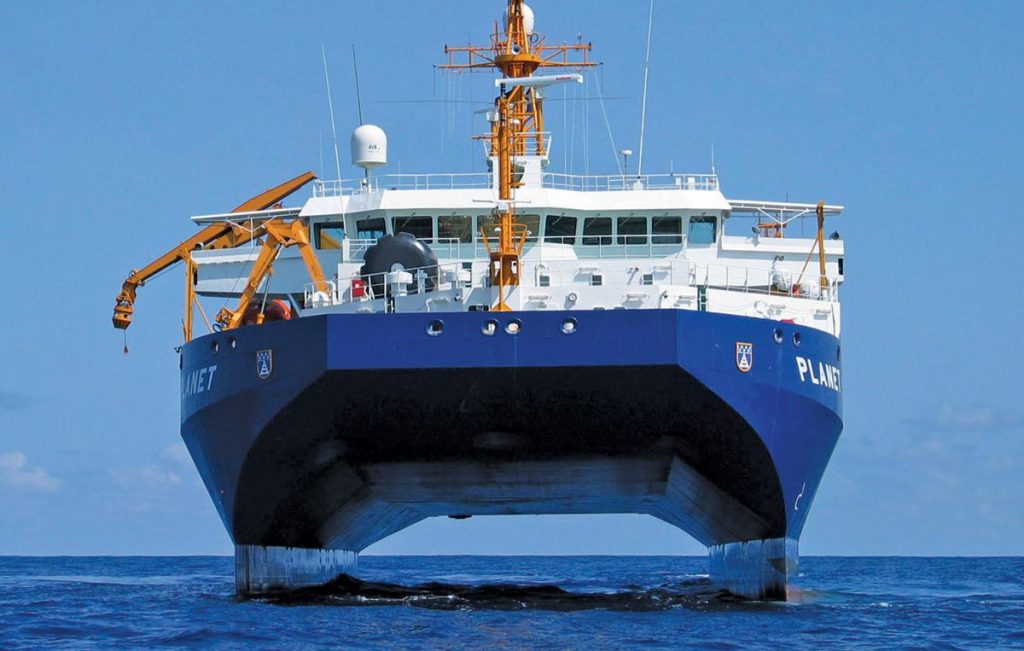
All SWATH vessels have a propeller each on each pod. The prime movers may be located within the pod, for hulls accommodating larger diameters. However, for hulls with low diameter pods, the engines are generally provided on the tween deck and the power is transmitted to the pods through bevel gears. Some designers even prefer to opt for water jet propulsion for smaller SWATH vessels, where the pump is housed on the tween deck and the tunnels are led to the pods.

Figure 6: SWATH Ocean Research Vessel.

Figure 7: SWATH Stealth Ship.
Hydrofoil Crafts:
A hydrofoil craft is one in which the lift force is generated during forward motion due to the presence of hydrofoils under its hull. However, they are to be operated at the optimum speed that corresponds to the maximum lift provided by the hydrofoil sections. Operation at speeds further away from the optimum lift region would result in an increase of power requirement since the lift is proportional to the square of the velocity.

Figure 8: A hydrofoil craft.
Note the hydrofoil sections under the hull in the above image. We will come into this type of hydrofoil crafts a little later, but what is important to understand is the added advantage of hydrofoils. When a hydrofoil craft operates at its optimum speed, there comes a point where the lift force generated by the hydrofoils lift the hull or a significant portion of the hull above the water surface (as you can see in the figures below). This reduces the wetted surface area, therefore reducing the frictional drag significantly.

Figure 9: Lifting of a hull from water due to hydrofoil action.
There are two types of hydrofoil crafts depending on the extent to which the hydrofoils are submerged during operation of the craft:
Surface Piercing Hydrofoil: In these crafts, a particular portion of the hydrofoils pierce out of the surface during full speed operation, and only a portion of the foils remains submerged, as shown in the image below. The principle behind these foils is simple. When the lift generated by the foil is sufficient enough to lift the hull above the water surface, the hull does not contribute to any resistance. After this stage, the lift required from the foils must be constant. Therefore, for an increase in speed, a reduction in submerged area of the hydrofoil is required. The surface piercing hydrofoil does exactly this as the craft rises higher with increasing speed. Similarly, when the speed reduces, the vessel comes down to the point where the submerged area of the foils is sufficient enough to keep the lift constant.

Figure 10: Surface piercing hydrofoil craft.
Incidence Controlled or Completely Submerged Hydrofoils: These hydrofoils are completely submerged in all sailing conditions, as the name suggests. They are positioned further under the hull by the use of A- struts. In order to maintain constant lift, the angle of attack of these hydrofoils is changed hydraulically during variation in speed. This is done by providing flaps within the hydrofoils, which give these crafts a self-stabilizing capability.
The longitudinal distribution of the hydrofoils can be achieved in three ways, as shown in the figure below. It is preferable to have a larger hydrofoil at the vicinity (just forward or aft) of the centre of gravity, and a smaller foil at the far aft for forward. This helps in achieving the optimum trim condition. However, some hydrofoils are arranged in tandem, that is, two large hydrofoils at equal distance aft and forward of the centre of gravity.

Figure 11: Different arrangements of hydrofoils.
Air Cushion Vehicles:
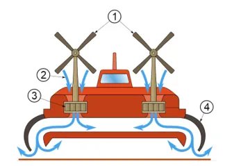
Air Cushion Vehicles (AIVs) are supported not by upward buoyancy force, but by an aerostatic cushion developed between the inflatable skirt and the water surface. The most common type of air cushion vehicles is a Hovercraft. A schematic diagram below will be used to explain the working of this craft.

Figure 12: Schematic operation of a hovercraft. (Source: wikimedia.org)
An ideal air cushion vehicle will have four major components which help in its propulsion:
1. Propellers.
2. Air.
3. Fan.
4. Flexible or Inflatable Skirt.
The first step in the sequence is drawing of air by the fans placed at the port and starboard sides. The air drawn by these fans are used to inflate the empty space in the skirt. As the air flows into the skirt, it forms a cushion of air between the skirt and the water surface. This chamber of air is also called Phlenum Chamber. This cushion provides a typical reaction which lifts the craft from the surface. Once the required lift has been generated, and the craft is not in contact with the surface, the air propellers are started to induce forward motion. Twin propellers help in easy manoeuvrability and direction changing abilities.
The skirt may be flexible or rigid, depending on the design of the vessel. However, the primary purpose remains the same. Usually, the side walls of the skirt are rigid to contain the air cushion within the skirt. The upward normal reaction due to the air cushion would act at the centre of pressure of the air chamber. Therefore, the displacement between the centre of gravity of the craft and the centre of pressure of the chamber would produce upsetting forces inducing unwanted trim and heel conditions. This is where the design of the skirt becomes an important part of hovercraft design. One way to combat this is to provide separate cushion compartments in the fore and aft, starboard and port. In such case, when the craft has “heeled” or trimmed to one side, the air in the lower side compartment is compressed, thus creating a righting moment.
Spray resistance, however, forms a significant portion of the total resistance of air cushion vessels. The large air propellers are provided with vectoring capability so as to compensate the effect of wind disturbances. Most of them are also provided with large surface area air rudders for directional control.
An Interesting Fact: While the hovercraft does not operate in contact with the water surface, why do they still generate wave systems when they move through water?
The cushion of air creates a dent on the water surface just under the skirt. Hence, as the craft moves, this dent on the water moves along with the craft. It is this moving indentation that causes a series of transverse and divergent wave systems. This also means that though a hovercraft may have significantly low frictional resistance, it does have a component of wave resistance. However, as the speed of the craft increases, there comes a point where the speed of the indentation cannot keep up with the vessel’s speed, therefore suddenly reducing the wave resistance. This is the optimum operating speed of a hovercraft.
Astronomical amounts of research are being conducted in the field of high-performance marine vehicles, especially by countries like US and Russia. Many experimental projects of surface effect ships have turned out to be failures; however, this has not deterred the efforts. The recent development of the Navies in hybrid crafts is one of the biggest examples.


Comments are closed