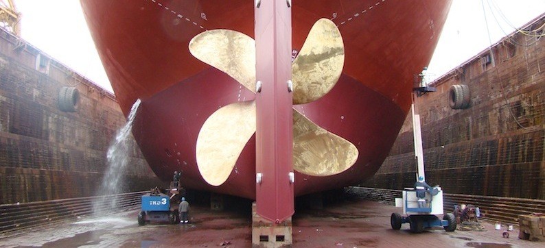
Propeller is the most significant machinery system of the ship. No matter what type of propeller it is, ship owners never make compromises on such important equipment as it directly affects the efficiency and safety of the vessel. Here we discuss about fixed pitch keyless propeller renewal.
Why is propeller renewed?
There are various reasons for which a ship’s propeller could be renewed. Some of the significant reasons are:
1) Damage to the propeller
2) Dynamically unbalanced
3) Renewing the existing propeller with a new propeller that is of better material, larger blade area etc.

Below we will learn about the procedures involved in renewing a propeller.
Before decoupling the intermediate shaft and the propeller shaft (tail shaft), make thorough inspection of the propulsion system. Generally, the shaft jack up test is done before removing the intermediate shaft.

Fig 1. Jack up test arrangement

Figure 2: Displacement VS. Load
Important points on Jack up test:
1) In jack up test we actually jack up the shaft to get vivid picture of the bearing reaction, the results need to be corrected
2) Hence, it is advised to place the hydraulic jack close to the bearing for better accuracy
3) To verify the results, ABS reaction Coefficient matrix can be referred wherein the expected gradient of the average line in the curve is tabulated (see the above figure).
Once the Jack up test is done, Intermediate bearing cap is removed, and then the intermediate shaft is removed prior to which the tail shaft is secured. It is very important to protect the bearing area. Necessary pad eyes need to be welded, make sure redundant pad eyes are welded and lifting arrangements are sufficient to take the load of the intermediate shaft. Another important thing to note is the location where the intermediate shaft can be secured.

Figure 3: Intermediate shaft removal

Figure 4: Intermediate shaft removal
Once the intermediate shaft is removed and secured in a safe location in the ship, check the condition of the plumber block bearings. Look for any white metal debris or contact marks.

Image 5: Intermediate shaft bearing
The tail shaft removal is done in the dry dock.
– For this, the first step is to cut the rope guard and keep it aside. Propeller cone is to be removed and then slack the aft stern tube seal (prior to which stern tube oil need to be drained).
– Then propeller nut is removed (make sure reference point is marked on the tail shaft) and the propeller is secured prior to the tail shaft removal.
– Lifting and shifting arrangements need to be pre-planned.
– Remove the forward stern tube seal and then pull the tail shaft and shift to the lifting zone; in some cases tail shaft can be removed through the skylight but in most cases it requires cutting ship side shell for access. Tail shaft is carefully pulled out through the stern tube and removed through the access. It is advised to perform NDT on the tail shaft taper area.

Figure 7: Tail shaft remova
Propeller –Tail Shaft Bedding
Propeller and tail shaft bedding reveals how good is the contact. This is done by applying Prussian blue to the tail shaft tapered area. The tail shaft is then lifted vertically and matted to the propeller hub which is positioned horizontally. The contact area in the hub is visually examined and the class requires at least 70-80% of contact. Blue mark zone on the hub is polished and process is repeated until you get 70-80% fit.

Figure 8: Propeller –tail shaft bedding

Figure 9: Propeller –tail shaft bedding
Propeller Mounting
On completion and satisfaction of propeller bedding, tail shaft and other accessories that are removed are installed back. Then the propeller is mounted. This is a significant stage and careful attention is paid during the same. Here we will discuss about the oil injection method for a keyless propeller mounting.
1) Clean the propeller boss and the propeller shaft
2) Slide the propeller to the propeller shaft and align to the match marks. (Prior to this step, remember to record the temperature of propeller boss and propeller shaft)
3) Screw in the Pilgrim Nut
4) Dry fit: Actuate the high-pressure pump connecting the Pilgrim nut, allow the propeller to slide in to certain distance and set the dial indicator to zero. The maker always recommends initial load
5)Wet fit: Then actuate the high pressure pump connecting the propeller boss expansion oil port and simultaneously actuate the nut pressure pump. Raise the pressure gradually until the predetermined push up length is achieved (determination of push up length is explained below)
6) Once the required push up length is achieved gradually release the pressure of boss expansion port and then release the nut pressure
7) Remove all the connections and plug both propeller boss port and pilgrim nut port
8) Remember to take shaft jack up test post the installation
9) Verify the coupling alignment using sag and gap method

Propeller mounting arrangement

Figure 10: Propeller push up arrangement

Figure 11: Propeller push up arrangement
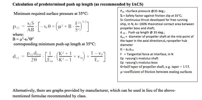
Calculation of predetermined push up length (as recommended by IACS)

Alternatively, there are graphs provided by manufacturer, which can be used in lieu of the above-mentioned formulae recommended by the class.
Permissible push up length can be captured for the corresponding temperature.
Conclusion
Propeller renewal is not about removing the existing propeller and just installing the new one, there are many other significant factors to overcome. Following are important points to be taken care of:
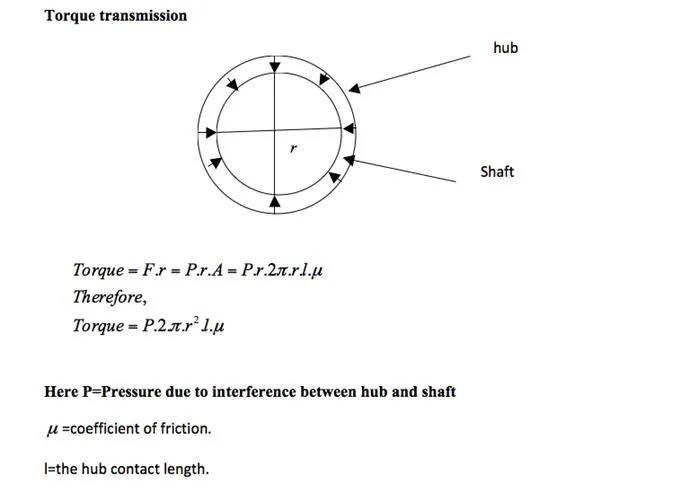
1) Good interference fit to transmit the torque: Damaging factor here is the varying temperature and differential thermal expansion of the propeller hub (bronze) and propeller shaft (steel).
Thermal expansion coefficient of bronze is about 10 and steel is about 7 (in 10-6 in/Fahrenheit). This will affect the fitting, hence keeping all this in mind required push up length is calculated such that the sufficient friction is achieved to transmit the torque.

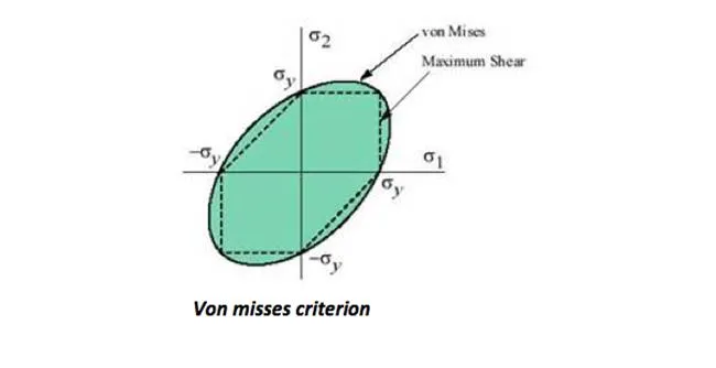
2) Reduced stress on propeller hub and propeller shaft: Von misses stress should be less than 0.7 times yield stress of propeller material. Von misses criterion is one of the most commonly used failure theory.
To assess the von misses stress:
1) Derive the stress elements
2) Find the principal stresses (Mohr’s circle)

3) From the principal stresses von misses stress can be derived (for 2d). If it is greater than the yield strength, then the material fails. It is just a simple explanation about von misses stress. Taking all these into account, maker represent the minimum push up length graphically.


Comments are closed