As ships continued to grow in size and became faster, modern systems easing human effort were incorporated. Basically, there are two types of commonly used steering gear systems present:
· Hydraulic
· Electro-hydraulic type
Though the system has undergone some major evolution, the basic physics of operation remains the same.
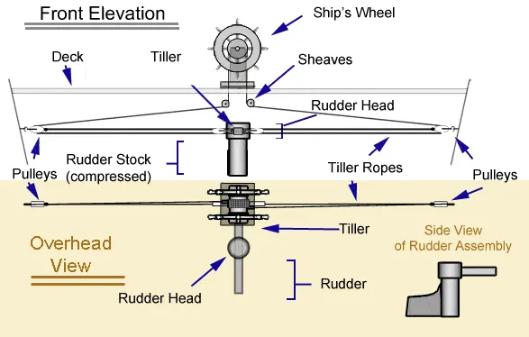
Figure 2: Modern day advanced steering control at helm
The main control of the steering operations is given from the helm of any ship, similar to an automobile where the entire control of the vehicle’s “steer-ability” rests on the steering wheel of the driver. The ‘control force’ for turning is triggered off from the wheel at the helm, which reaches the steering gear system.
The steering gear system generates a torsional force at a certain scale which is then, in turn, is transmitted to the rudder stock that turns the rudder. The intermediate steering systems of a modern day ship can be multifarious with each small component having its own unique function. We omit to discuss each and every such component in detail.
A better illustration for the exact work sequence of in a simple rudder system is given in the following figure.
Figure 3: Primitive Steering Gear System layout
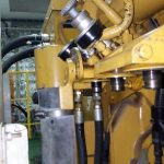
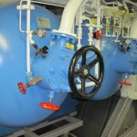
Figure 4: Representative image of Steering Gear arrangement in a ship
The rudder system consists of the following:
· Rudder actuators
· Power units
· Other auxiliary equipment needed to apply turn the rudder by applying torque
· Hydraulic pumps and valves
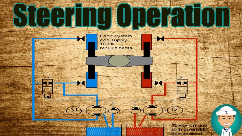
In hydraulic and electro-hydraulic systems, hydraulic pressure is developed by hydraulic pumps which are mainly driven by electric motors (electro-hydraulic systems) or sometimes through purely mechanical means (hydraulic systems).
However, mainly advanced electro-hydraulic systems are predominant in ships nowadays. These hydraulic pumps play a crucial role in generating the required pressure to create motions in the steering gear which can trigger the necessary rotary moments in the rudder system.
These pumps are basically of two major types:
· Radial piston type (Hele-Shaw)
· Axial Piston type (Swash plate)
Actuators mediate the coordination between the generated hydraulic pressure from pumps (driven electrically, of course) and the rudder stock by converting it into a mechanical force creating a turning moment for the rudder. Actuators are now mainly electrically driven by power units.
These actuators, in turn, can be of two types:
· Piston or cylindrical arrangement
· Vane type rotor
The types of actuator systems depict the types of steering gears present on ships, which are also segregated as Ram type and Rotary Vane type arrangements accordingly.
Ram Type Steering Gear System
Ram type steering gear is one of the commonly used steering gear construction and is quite expensive in construction. The basic principle is same as that of a hydraulically-driven motor engine or lift.
There are four hydraulic cylinders attached to the two arms of the actuator disc, on both sides. These cylinders are directly coupled to electrically driven hydraulic pumps which generate hydraulic pressure through pipes. This hydraulic pressure field present in the pumps imparts motion to the hydraulic cylinders, which in turn corresponds with the actuator to act upon the rudder stock. As we know, rudder stock is an indispensable part of the entire steering gear arrangement of ships and dictates the exact behaviour of the rudder response.
The sense of turning the rudder is guided by the action of the hydraulic pump. The physics behind its function can be explained better with the help of the following figure.
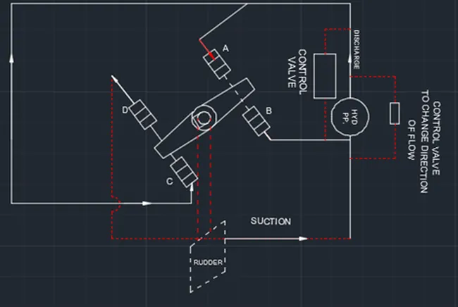
Figure 5: Ram type steering Gear
Here the cylinders denoted A and C are connected to the discharge side of the pump. This generates a positive pressure in the piston cylinders. On the contrary, the other two cylinders B and D are connected to the suction side of the pump. This creates a negative pressure in the cylinders. The resultant forces create a clockwise moment in the rudder. To put it simply, positive and negative pressures from pumps generate lateral forces on the rams which create a couple for turning the rudder stock.
Similarly, to put it in a anticlockwise turning sense, the reverse is carried out, viz. the discharge ends of the pumps are connected to the cylinders B and D, while the suction side of the pumps are to A and C. This reverse pressure flow from hydraulic pumps is achieved with the help of control valves operated from the wheelhouse.
The ram type steering gear arrangement produces a considerably high value of torque for a given applied power. The hydraulic oil pressure varies from 100 bars to 175 bars depending on the size of the rudder and torque required.
Rotary Vane Steering Gear
In rotary vane steering gear, there is a fixed housing in which two vanes rotate. The housing along with the vanes form four chambers. The physics behind its operation is similar to the ram type with a small difference.
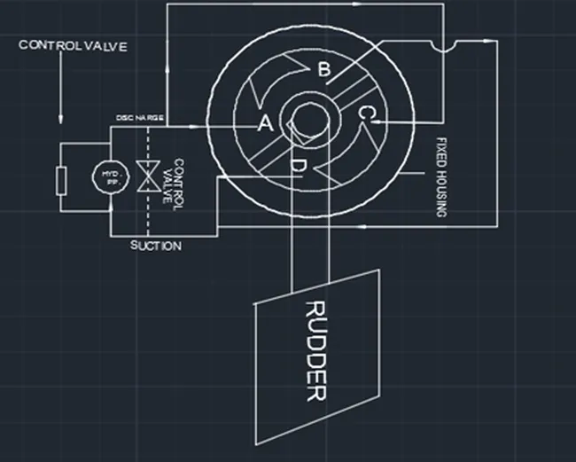
Figure 6: Rotary Vane type Steering Gear
When chambers A and C are pressurised, there is an anticlockwise rotation of the vanes. A and C are connected to the discharge side of the pump while chambers B and D are connected to the suction side of the pump.
Similarly, when clockwise rotation is required, B and D are connected to the discharge side of the pump while A and C are connected to the suction side of the pump. As above, this is also operated by specialised control valves.
Thus, differential pressurisation of the chambers cause rotational moments in the vane.
Rotary vane type arrangement is used when the pressure requirement is 60 to 100 bar for producing required torque. This is the main advantage of rotary vane type steering gear, requiring lesser hydraulic pressure and thus power for producing the same amount of torque as ram type.
There are 3 fixed and 3 moving vanes, which can make rudder angles up to 70 degrees, i.e 35 degrees on each side.
This arrangement has several other advantages like lower installation cost, less weight and smaller space required.
The fixed and rotating vanes are of spheroidal graphite cast iron. Keys are often provided in the rotary vanes for proper strength and orientation.
Comments are closed