Over recent years, many owners have elected to burn low grade residual fuels in medium-speed auxiliary engines, sometimes with disastrous results. Fuels bunkered for slow-speed main engines may be of too poor a quality for use in auxiliaries even where the engines have been designed for heavy fuel operation.
Major problems have been experienced on large slow-speed engines with some of the poor quality bunkers such as those containing catalytic fines. Fuel should conform to the specification given in the instruction book for the engine.
Typical of the medium-speed engines designed to be capable of running on heavy fuel are the Allen S12 series in-line engines having four, six, eight designated VS12 which are produced with twelve or sixteen cylinders.
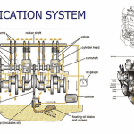
The in-line S12 engine structure (Figure 7.1) is based on a deep section cast iron bedplate and a cast iron A-frame of monobloc construction which are flanged and bolted together. The bedplate carries thin wall, steel-backed, white-metal or aluminium-tin lined main bearings.
An additional bearing is incorporated to carry the combined loads of the flywheel and part of the weight of the generator. Access doors are provided at the front and back. Those on the back of the engine are fitted with crankcase explosion relief valves. In this style of construction, which is common to many medium-speed engines, it is necessary to lift the A-frame if the crankshaft is to be removed. Some designs incorporate a C-frame arrangement which permits side removal of the crankshaft.
The one-piece alloy steel crankshaft is slab-forged, oil-hardened and tempered. A solid half coupling forged integrally carries the flywheel to which the generator is coupled. The main coupling bolts pass through the crankshaft half coupling, the flywheel and the generator half coupling; two additional bolts are incorporated to retain the flywheel on the crankshaft when the generator is uncoupled.
Additional machines such as an air compressor or a bilge pump may be driven from the free end of the crankshaft, through a clutch. Axial location of the crankshaft is maintained by renewable thrust rings. Drilled passages in the crankshaft feed oil from the main to the connecting rod bearings. In the S12-F engine these oil passages are arranged to provide a continuous supply of oil to the cooled pistons. Where necessary, balance weights are bolted to the crank-webs. In four-cylinder engines having cranks at 180°, secondary balancing gear is required (Figure 7.2).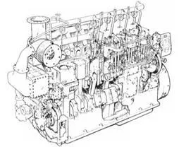
Figure 7,1 Six cylinder S12-F engine (APE-Allen Ltd)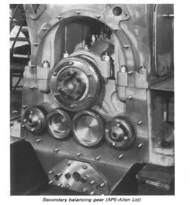
Figure 7,2 Secondary balancing gear (APE-Allen Ltd)
The connecting rods are H-section steel forgings, bored to carry oil to the gudgeon pin bush, which is a light interference fit in the rod. Crankpin bearings are thin-walled steel, lined with aluminium-tin, split horizontally and secured by four fitted bolts. Connecting rods of differing designs will be found in some engines. Thus the bottom end assembly for the Allen VS12 (vee engine) series (Figure 7.3) is made simple by axially displacing both banks of cylinders and having two connecting rod bottom end bearings on each crankpin.
The large end bearing is split diagonally to enable the connecting rod to be withdrawn through the cylinder. Bearing butts are serrated for location. Bronze bushes are used for the top ends; the large ends have steel backed, aluminium-tin bearings with an overlay which is deposited by plating.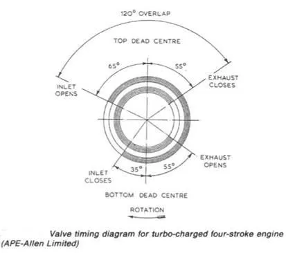
Figure 7.3 Valve timing diagram for turbo charged four stroke engine (APE-Atlen Limited)
The fully-floating gudgeon pin of the Allen S12 is steel, case-hardened and ground, retained in the aluminium alloy piston by circlips. The piston has an integrally cast alloy iron carrier for the top piston ring, two additional pressure rings and one slotted oil scraper ring, all above the gudgeon pin. Pistons for the S12-F are one-piece aluminium-alloy castings incorporating oil cooling cavities.
The oil provides intensive cooling of the piston particularly in the region of the ring belt. The wet-type close grained, cast iron cylinder liners, are supported by a flange at the top which is sandwiched between the cylinder head and a spigot with ring gasket, on the engine frame. To permit vertical expansion of the liner it is free to move at its lower end, a seal being effected by two synthetic compound O rings carried in grooves in the liner wall
Camshaft and cylinder head
The camshaft, is driven by a roller chain (some engines have a gear train). To allow accurate phasing of crankshaft and camshaft during initial set up and if timing has to be reset, elongated holes are provided at the coupling between the camshaft drive wheel and the camshaft. Adjustable packing pieces inserted into the elongated holes ensure that correct timing is maintained.
Lubrication of the camshaft bearings is by a forced feed system; an oiiway bored through the full length of the camshaft conducting the oil to the bearings. An extension of the camshaft at the driving end, is provided with a flexible coupling for the hydraulic governor and tachometer drive. The individual alloy cast iron cylinder heads have totally enclosed valve gear which is lubricated from the engine oil system. The S12-D engine has one inlet and one exhaust valve, the S12-F, because of its higher running speed, is fitted with heads having two inlet and two exhaust valves.
The valve pairs are parallel and operated by rocking levers and guided bridges. Each valve has two springs and Is fitted with a rotator. The valves seat in the cylinder heads on renewable inserts of iron alloy. The centrally placed fuel injector is situated between the valve covers so that fuel oil contamination of lubricating oil is avoided. This also enables the injectors to be withdrawn for servicing without disturbing the valve covers.
Fuel pump and timing diagrams
Separate camshaft-actuated helix-type fuel pumps are employed for each cylinder. These deliver fuel to the injectors which are set to lift at a pressure of 176 kg/cm2 on the S12-D and 211 kg/cm2 on the S12-F, Fuel pump delivery volume is controlled by a rack which alters the cut-off or spill point. The racks are linked through a control shaft to the engine governor which thus regulates the end of the fuel delivery period and hence the quantity of fuel delivered according to the power required. Fuel injection commences at approximately 15° before top-dead-centre and takes place over a period of about 35° of crank angle. Combustion should be completed within this period.
A typical valve timing diagram (Figure 7.3) shows the large overlap between the opening of the air inlet and closure of the exhaust compared with the previous normally aspirated engine (Figure 7.4) which is no longer produced. The overlap allows a through flow of charge air which is essential for exhaust valve cooling, particularly for an engine which operates using residual fuel.
Vanadium and sodium ash from the fuel tends to adhere to valves and seats if their temperature exceeds the melting point of the ash. The deposited ash itself causes surface damage in the form of pitting and also tends to prevent closure. Valve surface temperature should ideally not exceed 420°C if ash deposit is to be avoided. Localized high surface temperature can be prevented on that part of the valve adjacent to the fuel injector by the rotator. Valve surfaces can be protected by a stellite deposit or, alternatively, valves can be made from nimonic. The turbo-blower, mounted at the free end of the engine, has a filter/silencer fitted on the air intake. The charge air cooler is similar to that described in Chapter I,
Turbochargers
The turbocharger is driven by the exhaust gas leaving the cylinders of the diesel engine it serves. The gas has sufficient pressure and heat when released from the cylinder at exhaust opening, to drive the turbocharger. It is directed on to turbine blades by nozzles which are built into a nozzle ring in the axial flow type or into a radial turbine from the peripheral volute casing of smaller turbochargers.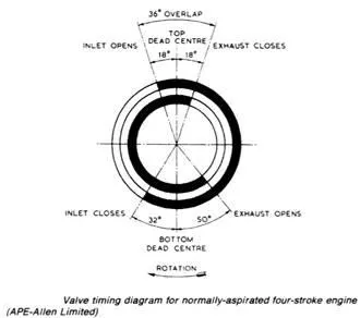
Figure 7.4 Valve timing diagram for normally-aspirated four-stroke engine (APE-Allen Limited)
A small turbocharger for a generator diesel prime mover may be driven by a radial flow gas turbine, which closely resembles the impeller it drives. This type of machine costs less to manufacture than the axial flow turbine, and has a simpler construction.
Turbocharger blades are rotated, partly by the impact of jets of gas from the nozzles and partly by the reaction, as gases leave the blades. Correct nozzle and blade shape is vital. Performance of turbocharger and engine can deteriorate seriously with sometimes very moderate surface marking due to erosion or corrosion.
Nozzle shape can be altered in service, by: 1 deposit build up; 2 corrosion of surfaces; 3 erosion, by solids entrained in the exhaust gas.
Oil refinery residuals are used in a blend with clean distillate fuels for economy in some engines. Deposits are common when heavy residual fuel is used. Regular cleaning is necessary to prevent nozzle blockage. Water washing rather than dismantling and cleaning is used for deposit removal. Fittings should be provided for water washing if an engine is to be operated using residual fuel.
Corrosion is a potential problem for the turbochargers of engines which operate using residual fuels containing vanadium, sodium and sulphur as impurities and in a marine environment where sodium chloride is present in the intake air. The impurities listed burn to form a number of different ash products which may adhere to surfaces at higher temperatures. Corrosion and surface damage follows breakdown of the protective film on the metal surface by ash compounds.
Remedies for these problems are based on designing for lower operating temperatures and regular water washing to remove the accumulated slag (ash). Corrosion problems are well known and documented in various technical papers such as those of the Institute of Marine Engineers.
Erosion by solids entrained in the exhaust gas is another potential problem. Catalytic fines (based on aluminium and silicon which are abrasive) will be present in some fuels and could cause surface damage to nozzles. Purification of fuels is necessary to remove solids and where catalytic fines are suspected, the use of centrifuges arranged as two purifiers in parallel or a purifier and a clarifier in series is recommended .