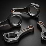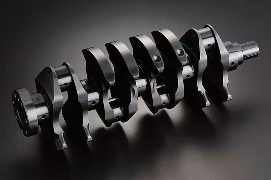
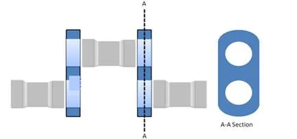
Crankshaft the word itself made of two words crank and shaft, or in another way we can say that a shaft which is made for a purpose of cranking. The crankshaft is a large component with a complex geometry in the engine, which converts the reciprocating displacement of the piston into a rotary motion. This conversion of the motion is achieved by the special design of the crankshaft, where the connecting point of the piston rod or connecting rod to the shaft is having an axial offset from the axis of the crankshaft. The high-pressure gasses formed by the burning fuel act on the piston top area and push the piston downwards. This force is transferred by the help of connecting rod at the axially offset point of the crankshaft, which produces a torque and hence a rotatory motion in the crankshaft. Here you can see a basic design and parts of a crankshaft
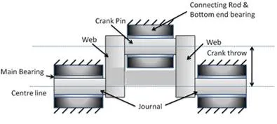
A section of the crankshaft
In this blog, we are going to discuss the various kind of shafts used for marine engines. The crankshaft is a very important and heavily stressed component of a diesel engine. These stresses and bending moments on crankshaft varies throughout the running cycle and depends upon various factors.
A diesel engine crankshaft is designed in such a way that, it can receive a unidirectional torque by all the units. To achieve this, the crank angle for the angular arrangement of each crank with respect to other depends on the number of strokes and number of the cylinder of the engine.
Types of crankshaft
On basis of construction, method crankshaft can be broadly divided into the following four categories:
Solid forged crankshaft
Here the whole crankshaft is forged or cast as on single piece. This kind of crankshaft is made for small engines. In this kind of forging provides continuity of material grain flow which allows the smooth transmission of stress and better fatigue resistance. Unfortunately, such crankshafts are limited to the smaller engines because there is a limit to the size of forging equipment and the size of steel bar which can be produced.
Fully Built Crankshaft
Full Built Crankshaft
As the name states, here all parts are manufactured separately by steel casting or forging and then assembled together by the use of shrink fitting. Their construction and design are very simple and easy replacement of any damaged parts are possible. All individual components (i.e., Main shaft, Crank Web and crank pin) are made and machined separately for the fitting faces.
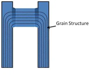
Grain structure of single unit build crankshaft
For proper shrink fitting calculation must be done with special care so that the friction between the pin and web is sufficient enough to transmit the torque without stressing the pin and web. Too large an allowance produces a high stress which can result in yield when the working stress is added where too small allowance can lead to slippage of shrink fitting. Normally this allowance is about 1/500-1/600 of the pin diameter but it may vary as per the type of material used for construction and the working temperature.
The main area of concern of this kind of shaft is the lack of grain flow and its web, which is designed with two holes and must have the considerable strength to allow two shrunk fits. That’s why very few large 2 strokes slow speed engines use fully build up the crankshaft
Semi Built Crankshaft
Semi Built Crankshaft
These type of crankshafts have the crank throws(crankpin and crank web forged together) as a single component and the main shaft general is shrunk fit to the web. As compared to fully build crankshaft, this has continuous grain flow across the crank pin and web. It gives better fatigue strength with small webs and lighter shaft weight. This type if crankshafts are more popular in large slow speed 2 stroke engine and large 4 stroke medium speed engines for their reliability.
Fully welded crankshaft
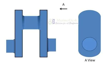
A section of full welded crankshaft
It was made up of a series of forgings each comprising of half a main journal, web, crankpin, second web, and half a main journal. These forgings were then welded together using a submerged arc welding process to form the crankshaft. After welding the journals were stress relieved and machined. As well as having the advantage of continuous grain flow, the webs could be made a thinner (no shrink fit to accommodate), leading to a lighter shorter crankshaft
Stress on Crankshaft:
Change in stress when piston is at TDC and BDC
Due to the nature of its operation, there are several types of stress which come to act upon the crankshaft of engines. The main loading stresses are;
§ Inertia loads or weight load of the piston, connecting rod and piston rod(in 2-stroke). Inertia load of these parts due to accelerating and deaccelerating motion of piston while moving up and down in stroke, whereas load due to weight is negligible in comparison to other forces when running, and it is the only load in a stopped condition.
§ Variable combustion gas load: The radial component causes the pin and webs to bend and twist. The tangential component causes bending stress in webs and torsion stress in the journal.
Gas and Inertia forces on the web of a crankshaft
§ Torsional vibration stress in web pins is due to the shaft being wound up under torsional load and unwound due to its own stiffness.
§ Axial vibration stress due to the repeated in.-plane flexing of webs and the reaction the intermittent propeller thrust.
Torsional stress on the web of a crankshaft
§ Hoop Stress on full built or semi built crankshaft.
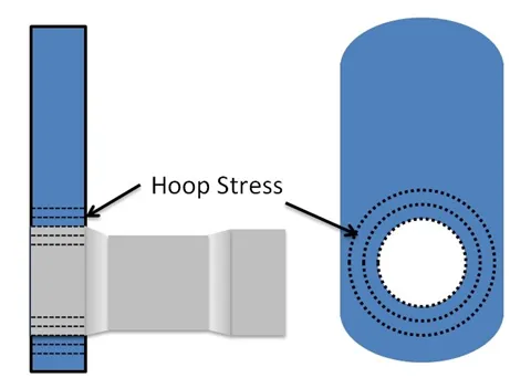
Hoop stress on web
Failure of Crankshaft
Due to these fluctuating loads sometimes the crankshaft may fail. Two major failure of crankshaft includes fatigue and cyclic stress failures. They are mostly due to high-frequency low loads or low-frequency high loads. The causes of crankshaft failures are:
Operational failure:
§ Main engine lubrication failure.
§ Poor support from bedplate foundation and tie rods, due to uneven tightening.
§ Severe operating conditions and overload(like uneven firing load on the crankshaft).
§ Torsional stresses giving a helical-shaped crack at 45 degrees to the axis of the pin.
§ Misalignment of main bearings.
§ Slippage of shrink fits only in a built type of crankshaft.
§ Corrosion fatigue due to lube oil turning acidic caused by lube oil contaminated by combustion products.
Manufacturing Defects:
§ Any sharp changes in a section where stresses get concentrated.
§ Lube oil passages, holes and drilling sections. The radii of the lube oil hole should be ample to reduce the stress concentration.
§ Surface defects(it can be an operational failure also) and sharp edges.
§ Pin to web fillet section should have ample radii.
§ Incorrect manufacture like slag inclusion and poor heat treatment.
One of the most common failures of the crankshaft is fatigue failure. In fatigue failure, a small crack generates at a stress raiser or any surface defect due to high fluctuating load on it. This crack will propagate smoothly for some time and will result in sudden brittle fracture of the crankshaft. To give sufficient fatigue strength to crankshaft following methods are used commonly during manufacturing:
§ Very smooth surface finish.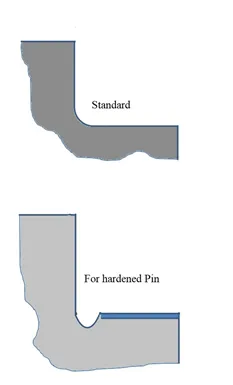
§ The sudden change in the shape of the crankshaft is avoided.
§ It is cold rolled(hardened pin) at radii areas of crankshaft where a change in stress(compression & tension) is frequent.
Material of Crankshaft:
§ High carbon steel(0.35 to 0.45 C) for slow speeds.
§ High carbon steel with alloys for medium-high speeds.
§ Chromium, tungsten, nickel, and magnesium alloys are used.
Slippage of the Crankshaft
Sometime due to uneven forces on built crankshaft may lead to slippage of the web with respect to the main journal. Most of the slippage is caused at the starting of the engine without blow through or overloading due to the faulty combustion process. The slippage in crankshaft increases vibration and stress on the engine, which further leads to complete failure of the engine. To find out slippage of crankshaft reference marks are marked on web and journal.
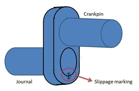
Slippage marking between web and journal
A small slippage can be taken care onboard, provided that the lube oil can pass through the crankshaft holes. To run the engine with smaller slippage following steps to be taken:
§ Change the timing of the exhaust valve with a corresponding timing after new slippage.
§ Change the timing of the fuel injection.
§ Run engine on low load.
The timing change of the exhaust valve and the fuel pump is very easily achievable in an electronic engine, but require lots of hard work in camshaft engines.
For larger slippage, ship staff has to call shore workshop to carry out this repair. This shrink fit has to be readjusted with cooling pin in nitrogen and heating web. In this case, also the surface of the fit will get distorted and these parts should be replaced as soon as possible to increase the life of the engine.