Fracture toughness is an indication of the amount of stress required to propagate a preexisting flaw. It is a very important material property since the occurrence of flaws is not completely avoidable in the processing, fabrication, or service of a material/component. Flaws may appear as cracks, voids, metallurgical inclusions, weld defects, design discontinuities, or some combination thereof. Since engineers can never be totally sure that a material is flaw free, it is common practice to assume that a flaw of some chosen size will be present in some number of components and use the linear elastic fracture mechanics (LEFM) approach to design critical components. This approach uses the flaw size and features, component geometry, loading conditions and the material property called fracture toughness to evaluate the ability of a component containing a flaw to resist fracture.
A parameter called the stress-intensity factor (K) is used to determine the fracture toughness of most materials. A Roman numeral subscript indicates the mode of fracture and the three modes of fracture are illustrated in the image to the right. Mode I fracture is the condition in which the crack plane is normal to the direction of largest tensile loading. This is the most commonly encountered mode and, therefore, for the remainder of the material we will consider KI
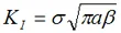
The stress intensity factor is a function of loading, crack size, and structural geometry. The stress intensity factor may be represented by the following equation:
| Where: | KI | is the fracture toughness in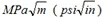 |
| s | is the applied stress in MPa or psi | |
| a | is the crack length in meters or inches | |
| B | is a crack length and component geometry factor that is different for each specimen and is dimensionless. |
Role of Material Thickness
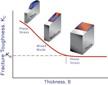
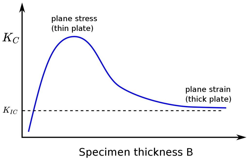
Specimens having standard proportions but different absolute size produce different values for KI. This results because the stress states adjacent to the flaw changes with the specimen thickness (B) until the thickness exceeds some critical dimension. Once the thickness exceeds the critical dimension, the value of KI becomes relatively constant and this value, KIC , is a true material property which is called the plane-strain fracture toughness. The relationship between stress intensity, KI, and fracture toughness, KIC, is similar to the relationship between stress and tensile stress. The stress intensity, KI, represents the level of “stress” at the tip of the crack and the fracture toughness, KIC, is the highest value of stress intensity that a material under very specific (plane-strain) conditions that a material can withstand without fracture. As the stress intensity factor reaches the KIC value, unstable fracture occurs. As with a material’s other mechanical properties, KIC is commonly reported in reference books and other sources.
| Plane Strain – a condition of a body in which the displacements of all points in the body are parallel to a given plane, and the values of theses displacements do not depend on the distance perpendicular to the planePlane Stress – a condition of a body in which the state of stress is such that two of the principal stresses are always parallel to a given plane and are constant in the normal direction. |
Plane-Strain and Plane-Stress
When a material with a crack is loaded in tension, the materials develop plastic strains as the yield stress is exceeded in the region near the crack tip. Material within the crack tip stress field, situated close to a free surface, can deform laterally (in the z-direction of the image) because there can be no stresses normal to the free surface. The state of stress tends to biaxial and the material fractures in a characteristic ductile manner, with a 45o shear lip being formed at each free surface. This condition is called “plane-stress” and it occurs in relatively thin bodies where the stress through the thickness cannot vary appreciably due to the thin section.
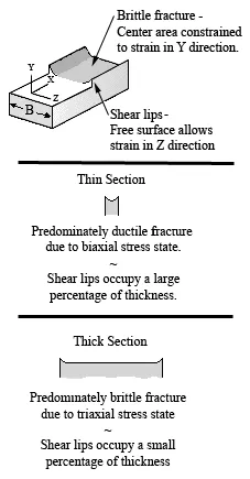
However, material away from the free surfaces of a relatively thick component is not free to deform laterally as it is constrained by the surrounding material. The stress state under these conditions tends to triaxial and there is zero strain perpendicular to both the stress axis and the direction of crack propagation when a material is loaded in tension. This condition is called “plane-strain” and is found in thick plates. Under plane-strain conditions, materials behave essentially elastic until the fracture stress is reached and then rapid fracture occurs. Since little or no plastic deformation is noted, this mode fracture is termed brittle fracture.
Plane-Strain Fracture Toughness Testing
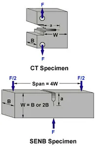
When performing a fracture toughness test, the most common test specimen configurations are the single edge notch bend (SENB or three-point bend), and the compact tension (CT) specimens. From the above discussion, it is clear that an accurate determination of the plane-strain fracture toughness requires a specimen whose thickness exceeds some critical thickness (B). Testing has shown that plane-strain conditions generally prevail when:
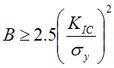
| Where: | B | is the minimum thickness that produces a condition where plastic strain energy at the crack tip in minimal |
| KIC | is the fracture toughness of the material | |
| sy | is the yield stress of material |
When a material of unknown fracture toughness is tested, a specimen of full material section thickness is tested or the specimen is sized based on a prediction of the fracture toughness. If the fracture toughness value resulting from the test does not satisfy the requirement of the above equation, the test must be repeated using a thicker specimen. In addition to this thickness calculation, test specifications have several other requirements that must be met (such as the size of the shear lips) before a test can be said to have resulted in a KIC value.
When a test fails to meet the thickness and other test requirement that are in place to insure plane-strain condition, the fracture toughness values produced is given the designation KC. Sometimes it is not possible to produce a specimen that meets the thickness requirement. For example when a relatively thin plate product with high toughness is being tested, it might not be possible to produce a thicker specimen with plain-strain conditions at the crack tip.
Plane-Stress and Transitional-Stress States
For cases where the plastic energy at the crack tip is not negligible, other fracture mechanics parameters, such as the J integral or R-curve, can be used to characterize a material. The toughness data produced by these other tests will be dependant on the thickness of the product tested and will not be a true material property. However, plane-strain conditions do not exist in all structural configurations and using KIC values in the design of relatively thin areas may result in excess conservatism and a weight or cost penalty. In cases where the actual stress state is plane-stress or, more generally, some intermediate- or transitional-stress state, it is more appropriate to use J integral or R-curve data, which account for slow, stable fracture (ductile tearing) rather than rapid (brittle) fracture.
Uses of Plane-Strain Fracture Toughness
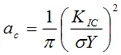
KIC values are used to determine the critical crack length when a given stress is applied to a component.

| Where: | sc | is the critical applied stress that will cause failure |
| KIC | is the plane-strain fracture toughness | |
| Y | is a constant related to the sample’s geometry | |
| a | is the crack length for edge cracks or one half crack length for internal crack |
KIC values are used also used to calculate the critical stress value when a crack of a given length is found in a component.
| Where: | a | is the crack length for edge cracks or one half crack length for internal crack |
| s | is the stress applied to the material | |
| KIC | is the plane-strain fracture toughness | |
| Y | is a constant related to the sample’s geometry |
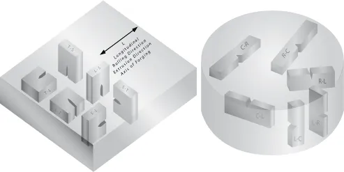
Orientation
The fracture toughness of a material commonly varies with grain direction. Therefore, it is customary to specify specimen and crack orientations by an ordered pair of grain direction symbols. The first letter designates the grain direction normal to the crack plane. The second letter designates the grain direction parallel to the fracture plane. For flat sections of various products, e.g., plate, extrusions, forgings, etc., in which the three grain directions are designated (L) longitudinal, (T) transverse, and (S) short transverse, the six principal fracture path directions are: L-T, L-S, T-L, T-S, S-L and S-T.