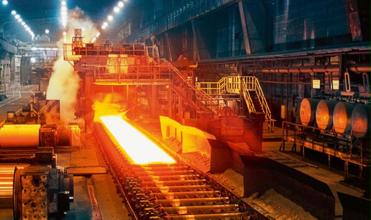
Non-Destructive Testing
This is carried out on components rather than on test pieces, they are designed to indicate flaws occurring due or after manufacture. They give no indication of the mechanical properties of the material.
Surface flaws may be detected by visual means aided by dye penetrant or magnetic crack detection. Internal flaws may be detected by X-ray or ultrasonic testing.
In addition to this there are special equipment able to exam machine finish.
Liquid Penetrant Methods
The surface is first cleaned using an volatile cleaner and degreaser. A fluorescent dye is then applied and a certain time allowed for it to enter any flaws under capillary action. Using the cleaning spray, the surface is then wiped clean. An ultra violet light is shone on the surface, any flaws showing up as the dye fluoresce.
The more commonly used Dye penetrant method is similar in application. The surface is cleaned an d the low viscosity penetrant sprayed on. After a set time the surface is again cleaned. A developer is then used which coats the surface in a fine white chalky dust he dye seeps out and stains the developer typically a red colour.
Both these methods are based loosely on the old paraffin and chalk method.

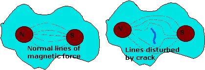
Magnetic crack detection
A component is place between two poles of a magnet The lines of magnetism concentrate around flaws. Magnetic particles are then applied, in a light oil or dry sprayed, onto the surface where they indicate the lines of magnetism and any anomalies. This method of testing a has a few limitations. Firstly it cannot be used on materials which cannot be magnetised such as austenitic steel and non-ferrous metals. Secondly it would not detect a crack which ran parallel to the lines of magnetism.
Fatigue
Most engineering component failure is due to fatigue. Fatigue may be defined as the formation and gradual propagation of a crack through a material under conditions of varying tensile stress. The stress must be tensile, cracks will not open up during compressive stress, and it must vary with time, fatigue cracks do not propagate under static tensile stress. A fatigue failed component exhibits two distinct types of surface on its fractured faces. There is the shell line marks of the fatigue crack growth, this may actually be polished due to the rubbing of the crack faces together, and the very rough section of final failure where the remaining material was unable to withstand the applied load causing final failure in a brittle manner.
The relative areas of fatigue crack growth and final failure indicate the type of loading and stress application involved. A large fatigue crack indicates low stress application involved. A large fatigue crack indicates low stress high cycles type of fatigue because the crack has taken a long time to propagate through the material, the relatively small final fracture surface indicates that low stress has been applied. (an example of this is a slightly misaligned motor coupling.) A small fatigue crack surface area but large final brittle failed area indicates low cycle high stress fatigue such as may be found in a pressure vessel like a starting air reservoir.
There is a very close connection between fatigue stress and the number of cycles to failure and this may be seen on the graph for steel.

There is a very close connection between fatigue stress and the number of cycles to failure and this may be seen on the graph for steel.
From this graph it can be seen that on the sloping section there is a set number of cycles to failure for any given stress. This means that the designer must make the dimensions of his component such that the stress induced will not exceed the value for that number of cycles. Alternately he may already have a set working stress and may then determine a safe working life for his component.
Operating speed of the engine must be taken into account when determining the expected lifetime in hours, the faster the machine operates the fewer the number of hours will be needed to reach the number of cycles. This is why bottom end bolts for medium speed engines require changing after a set number of hours whilst those for slow speed engines last much longer. The idea is to replace the bolts before there is any risk of fatigue failure.
There is a value of stress, known as the fatigue limit, where the graph is horizontal. If the stress is kept below this value fatigue failure should, theoretically, never occur. In practice problems can result due to stress raisers as these act to increase the stress locally to much higher values and so cause fatigue failure to take place before it was expected or when when it was not expected at all. These stress raisers include internal material defects such as slag, gas porosity, and existing cracks, but they may also be due to sharp changes in section caused by poor design or surface damage. Fillet radii should be used to avoid such stress raisers at changes in section and often these fillets are rolled because that avoids cutting the material grains and at the same time induces a compressive stress locally which reduces the total tensile stress in the material when working stress is applied. Undercutting the bolt diameter below the root of screw threads avoids the stress raiser effect of these threads and means that the nominal bolt diameter should not be subject to stress raiser effects.
Surface damage during overhaul causes stress raiser effects whilst overtightening of bolts induces a higher static stress so that when working stress is applied very high tensile stresses are obtained causing increased risk of fatigue.
The fact that a crack is not very large on the surface of a component does not mean that serious cracking does not exist. Only by seeing the full extent of a crack internally can the situation be fully assessed, this requires the use of ultrasonic methods. Even then some idea as to the type of loading must be obtained so that the real situation may be known. A small crack may not be near to causing failure with low stress fatigue but a crack of the same dimension may be very close to causing failure with high stress fatigue. In some situations such as piston crown it may be very difficult to detect cracks due to scale and other deposits.
Welds are particularly susceptible to fatigue cracking not because they are highly loaded but because slag and other defects they contain act as stress raisers. The presence of residual tensile stress in a weld also increases the total value of tensile stress when load is applied. Vibration imparts a varying load and many fatigue failures in welds are caused by vibration. Stress due to vibration may be very low but when stress raiser effects and residual stresses are added then the effect is appreciable. Any additional loading on a weld is liable to cause problems. This was the case with the Sulzer engine when jacking screws where first employed for holding the bearing caps as these jacking screws acted upwards on the cross section of the A-frames inducing a stress which was not there previously. Fatigue cracks developed in the weld of the A-frame but this was overcome by extending the cross plates and weld. Then machining a final radius.
Lower sections of bedplate transverse girders are highly stressed in a tensile manner and so are likely to have fatigue cracks
Corrosion in metals
Galvanic Action
Corrosion within cooling systems can occur if the coolant, i.e. water, has not been properly treated. The corrosion can take the form of acid attack with resultant loss of metal from a large area of the exposed surface, or by Oxygen attack characterised by pitting. A primary motive force for this corrosion is Galvanic action
The Galvanic Series.
Or Electromotive series for metals
Cathode
Gold and Platinum
Titanium
Silver
Silver solder
Chromium-Nickel-Iron (Passive)
Chromium-Iron (Passive)
Stainless Steel (Passive)
Copper
Monel
70/30 Cupro-Nickel
67-33 Nickel-Copper
Hydrogen
lead
Tin
2-1 Tin lead Solder
Bronzes
Brasses
Nickel
Stainless-Steel 18-8 (Active)
Stainless Steel 18-8-3 (Active)
Chromium Iron (Active)
Chromium-Nickel-Iron (Active)
Cadmium
Iron
Steel
Cast Iron
Chromium
Zinc
Aluminium
Aluminium Alloys
Magnesium
Anode
The metals closer to the anodic end of the list corrode with preference to the metals towards the cathode end.
A galvanic cell can occur within an apparently Homogeneous material due to several processes on of which is differential aeration where one area is exposed to more oxygen than another. The area with less oxygen becomes anodic and will corrode.
Galvanic action within metal

Galvanic action due to temperature gradient

This situation can exist in cooling water systems with complex layout of heat exchangers and passage ways within the diesel engine. Systems containing readily corrodible metals such as zinc, tin and lead alloys can complicate and intensify problems by causing deposit formations.
Differential Aeration
-Where only a single metal exists within a system corrosion can still take place if the oxygen content of the electrolyte is not homogenous. Such a situation can occur readily in a jacket water system as regions of stagnant flow soon have the oxygen level reduced by the oxidation of local metal. The metal adjacent to water with reduced levels of oxygen become anodic to metals with higher oxygen content electrolyte in contact with it. Generally, the anodic metal is small in comparison the cathode i.e. the area of stagnant flow is small compared to the area of normal flow of electrolyte, and high rates of corrosion can exist. One clear case of this is the generation of deep pits below rust scabs.
Corrosion of Metals
Steel (Fe)
Will readily corrode by the reaction with oxygen in the water primarily by galvanic action.
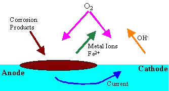
The Iron reduces to Iron ions at anode, the oxygen is reduced by combining with water and electrons passed from the anode (by iron changing to ions) to hydroxyl ions. Temperature, pH and the concentration of oxygen all affect the rate of corrosion.
The oxygen reacts with the Fe2+ to form Hematite (Fe2O3) . This is a reddish brown loose deposit. With reduced oxygen content the formation of Magnetite (Fe3 O4) will occur. This is a more tenacious layer and forms a protective boundary on the metal preventing further corrosion. This layer may be removed in low pH or high pH conditions.
Scabs and tubercles of Ferric oxides and Ferric hydroxides form over an active pit.
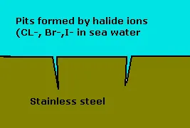
Stainless Steels
These are alloys of steel with high chromium content (around 11%). The alloying process results in a material with excellent corrosion resistance. Oxygen combines with the chromium and iron to form a tenacious self healing oxide layer.
The disadvantage of stainless steel is that in low oxygen environments, such as boil feed, the corrosion resistance is actually reduced. In addition stress corrosion cracking and pitting can occur when in the presence of chlorine ions. In this way stainless steel is not recommended in situations were stagnant sea water might exists at it could perforate quicker than mild steel. The chlorine ions are the correct right size to enter the atomic matrix of the metal and their concentration accelerates corrosion by the propogation of cracks. Catastrophic failure can occur.
Copper(Cu) and Copper alloys
Used in heat exchangers due to there high heat conductivity. Copper corrosion in oxygenated water is slow due to the time taken for oxygen to diffuse throught the oxide layer.
As copper is a relatively soft metal water velocities must be kept low. Its presence can lead to heavy pitting if deposited in steel systems. Ammonia in the water can remove the oxide layer and promote rapid corrosion
Aluminium (Al)
Is essentially inert in neutral water up to about 180’C. It is ampoteric meaning it will corrode rapidly in high and low pH conditions. In the presence of Sodium Carbonate or sodium hydroxide at pH above 9 this corrosion is particularly severe. These conditions may exist were boiling occurs concentrating hydroxyl ions.
Zinc (Zn)
Is anodic to steel and is often used as a protective coating on steel in a process called galvanising. It is ampoteric, corrosion increases in high and low pH conditions.
Note! At temperatures above 60’C the anodic/cathodic relationship with steel is reversed. This is of particular importance in engine cooling systems. The author has joined a vessel were the third engineer was merrily fitting anodes to the cylinder heads of a daihatsu generator engine. The fact that the engine was fresh water cooled with inhibitor treatment also was ignored
If galvanised pipes are to be fitted in a cooling circuit the coating must first be removed by controlled acid washing.
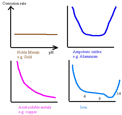
Factors affecting corrosion rates
Temperature
As a rule of thumb for each 10’C rise in temperature doubles the rate of corrosion.
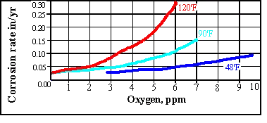
The rate of oxygen diffusion increases in an open system with temperature up to around 80’C. A rapid tailing off then occurs due to the solubility of oxygen. For this reason open system feed tanks seen on many vessels have heating coils which maintain the temperature at 85’C or higher.. In a closed system there is no such tail off as the oxygen cannot escape

pH/Alkalinity
The electrochemical nature of the metal will determine its corrosion rate with respect to pH. The corrosion rate of iron reduces as the pH increases to about 13 due to the reduced solubility of the Fe ions. Aluminium and zinc, being ampoteric, have rates of corrosion that increases with pH higher or lower than neutral
Materials used in ships sea water systems
90/10 Cupro-nickel
1. Resistant to high sea water velocities allowing reduced tube diameters
2. Resistant to corrosion under stagnant flow conditions and pitting
3. Resistant to clogging from marine growth
4. Ease of manufacture and welding
5. Reasonable cost
Stainless steel
Suffers from deep pitting in stagnant waters-if cleaned regularly this pitting can be reduced.

Comments are closed