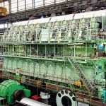
The invention of the diesel engine in 1893 has been attributed to Rudolf Diesel, a German mechanical engineer and inventor. This was an innovative internal combustion engine that was the fore-runner of today’s marine diesel engines used in ships worldwide.
I was first introduced to a marine diesel engine in the form of a Caterpillar (CAT) inboard engine in my Uncle Jimmy’s boat that he used for lobster/crab potting and local fishing trips. I accompanied him on many trips from when I was about ten years old and got to know the CAT engine’s idiosyncrasies quite well.
I them worked on much larger engines while serving my apprenticeship at Harland and Wolff of Belfast; they had a license to build Burmeister and Wain two-stroke diesel engines.
Leaving the shipyard in 1966, I joined my first ship in Portland Maine, the MV Orama, a 30,000T Oil Tanker, as Junior Engineer Officer. She had a B&W main engine so I felt quite at home, except for rolling about across the North Atlantic and gas-freeing of the tanks. Like all first trippers, I suffered from sea sickness for a few days, from a combination of her gyrations and the constant smell of crude oil.
The following sections supply links to marine articles here at Bright Hub that deal with diesel engines. After a brief introduction to the theory and terminology involved, we will move on to examining the components and systems of these engines, and then watch keeping duties, along with the operation and maintenance of a typical two-stroke marine diesel engine.
Engine Installation, Two Stroke & Four Stroke Engines
Before we examine the two-stroke and four-stroke engines, it is worthwhile to have a look at one method of assembling the engines in the engine room.
Engine Assembly aboard Ship
There are a number of marine diesel engine manufacturers who assemble and test the engines before stripping them down to the main components and lowering them into the ship’s engine room. We used to re-assemble the components in the engine room in the following order. (I imagine the same procedures are used today, except for the main foundation components being of a more modern design.)
The bed plate consists of two longitudinal girders, braced by cast steel traverse cross sections. At selected cross sections, the main bearing pockets are line-bored and two vertical holes drilled through them and the section. The main tie-rods are fitted through these into the bed plate.
The bed plate is lowered into position onto the supports that form part of the ship’s hull, then shimmed level and caulked before being fitted with hold-down bolts that run right around the bottom support frame. The crankshaft main bearing bottom halves are then fitted to the bed plate bearing pockets and the crankshaft lowered into them. The top halves of the main bearing are then fitted and checked for clearance and alignment.
The “A” frames and entablatures follow, being bolted together using fitted bolts, before other components are quickly fitted until the engine is completely rebuilt.
There are two types of marine diesel engines: two-stroke and four-stroke.
Two Stroke Cycle
Starting with the piston at bottom dead center (BDC), the combustion air is supplied to the liner air inlet ports and the piston starts to rise up the liner. Depending on the scavenging system, the piston either ejects the previous cycle exhaust gases out exhaust ports in the liner or out through an exhaust valve in the cylinder head.
The combustion air continues to be compressed to almost top dead center (TDC) when the fuel is injected and combusted by compression ignition, forcing the piston back down the liner.
Four Stroke Cycle
1. Exhaust Stroke – Starting again with the piston at BDC, it begins to rise up the liner, with the exhaust valve in the cylinder head opening and expelling the exhaust gasses during the upward stroke.
2. Inlet Stroke – The inlet valve now opens and combustion air is drawn in as the piston continues downwards.
3. Compression Stroke – After reaching BDC the piston starts to rise again and the inlet valve shuts.
4. Ignition/Power Stroke – As the piston continues to rise with both valves shut, and just before TDC, fuel is injected and is combusted through compression ignition, forcing the piston downwards on its power stroke.
Components of a Marine Diesel Engine
The marine diesel engine has changed a bit since I was an engineer at sea in the 1960’s. In those days the popular engines were Sulzer, B&W, British Polar, and Doxfords. Most shipping companies had a preference for a particular make of engine and had these installed in all their ships. This gave continuity for their Engineer Officers, who were both watch keepers and maintenance engineers combined.
Nowadays, modern diesel engines being manufactured by Wartsila Sulzer and MAN/B&W have recorded a thermal efficiency of over 50 percent. The Wartsila Sulzer RT96 flex-C is one of the world’s largest marine diesel engines: the14-cylinder model produces 108,000 horse power.
Cylinder Head
○ Cylinder Head
○ Cylinder Relief Valve
○ Air Start Valve
○ Fuel Oil Injector
○ Exhaust Valve
○ Main Engine Firing Order
Cylinder Liners
○ Cylinder Liners
Pistons
○ Pistons
○ Piston Rings
○ Piston Oil Cooling
○ Piston Water Cooling
Turbo Blowers
○ Turbo-blowers
Thrust Block
○ Thrust Block
Watch Keeping Duties & Engine Room Layout
Most engine rooms follow a basic design that has stood the test of time. This includes the location of the main and auxiliary engines, pumps, coolers, and prop-drive shafting, allowing the watch keeping engineers to acquaint themselves quickly when joining a new ship.
Fire and Explosion in the Main Engine & Engine Room
Fire and explosion aboard ship is still the most feared condition by today’s seafarers. The ship’s engine room is particularly susceptible to fire due to the hot surfaces and pipes carrying the fuel and lube-oil.
In today’s ships the crew is trained in firefighting both while at sea and by courses when on leave. This has led to the formation of fire teams who are competent at extinguishing all types of shipboard fires and rescuing the survivors of explosions.
Fire and Explosion – Main Engine
○ Oily Mist Detection of Crankcase Explosion
○ Cause, Control and Prevention of Scavenge Fires
Fire in Engine Room
○ CO2 Fire Protection for Machinery Spaces
○ Engine Room Fire Protection System
○ Engine Room Fire Fighting
Main & Auxiliary Engine Breakdown at Sea
When the main engine or generators break down at sea, it is the responsibility of the ship’s engineer officers to repair them. Sometimes there are no spare parts, so these have to be made by the engineers using the quite extensive engine room workshop. Major repairs can take a long time. I remember one occasion where we broke down in the Red Sea and were working for twenty hours to effect repairs. Then I stood my watch, totaling 24 hours on my feet. Fortunately this is the exception rather than the rule, and nowadays engines are more reliable and a better selection of spares is carried by the major shipping companies.
Repairs to Main Engines & Generators at Sea
○ The Main Repairs Carried out at Sea
○ Repairs to Main and Auxiliary Engines at Sea
○ Breakdown & Repair of Main Engine at Sea
I Learned from That
We have an old saying in Ireland that “Stranger things happen at sea.”
This reminded me of a few articles I wrote about accidents at sea and what I had learned from them. Please use the links below to find out more about these “learning curves” that happened to me and other sea-going engineers. Remember that this is how we learn- and sure isn’t hindsight a great thing!
Accidents in the Engine Room
○ Screw Compressor Failure
○ Oil Level Gauge Led to Failure of Purifier
○ Hotwell overflow causes boiler failure
○ Failure of Engine Room Overhead Crane Brakes
○ Removal of Exhaust Valve Seat
Accidents outside the Engine Room
○ Bad Communication Causes Damage to Ship’s Prop


Comments are closed