The primary function of watertight bulkheads is to divide a ship into a number of watertight compartments. Though most watertight bulkheads are transverse in orientation, some ships also have longitudinal watertight bulkheads within a compartment for longitudinal compartmentalisation within a compartment. Other than watertightness, the transverse bulkheads also add to the transverse strength of the ship. We will look into that aspect a little later.
In small ships, a transverse bulkhead may be constructed from a single plate. However, for larger ships, the plating of a transverse bulkhead usually consists of a series of horizontal strakes welded together. But what’s interesting here is that, the thickness of these strakes increase with depth, in order to strengthen the bulkhead against the maximum hydrostatic pressure in case the compartment is fully flooded. So prior to erection, two dimensional strakes are first cut out from plates of different thicknesses.
The bulkhead plate itself is not resistant enough against large scale transverse forces like shear forces. So they are stiffened, either vertically or horizontally. But we usually go for the vertical stiffening instead of the horizontal. Why? Because horizontal stiffening in ships with high beam would require stiffeners of long span, which would also increase the scantling and weight of the stiffener, affecting usable cargo volume. However, with vertical stiffening, the span (and hence, the scantling) of the stiffener can be kept low by introducing a stringer at mid-depth (a stringer acts as a fixed end, therefore reducing the span).
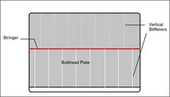
Figure 2: Vertical stiffening of a transverse watertight bulkhead.
The sections used for stiffening the bulkheads are usually flat bars, angles or bulb bars, depending upon the required section modulus. An important aspect of the design of bulkhead stiffeners is meeting the end conditions. In order to meet the boundary conditions so that the stiffeners respond as per the theoretical calculations, their end supports must be designed accordingly. At the upper end, they are attached to the underside of the deck plating with brackets, providing a hinged boundary condition. To achieve fixed ends, they are welded directly to the deck plate and the stringer.
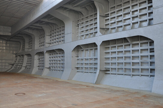
Most modern day ships use an advanced technology to achieve the required strength of bulkhead plates. They use corrugated bulkheads instead of stiffened ones. The corrugations are in the vertical direction, except when the breadth of the bulkhead is significantly low. However, there is one trade-off that needs to be made here. Since the corrugations are provided on the bulkhead plate right in the early fabrication stage, corrugated bulkheads are made of plates having uniform thickness (which is, the thickness equal to the lower most strake in case of a conventional bulkhead). This increases the weight of the bulkhead when compared to a conventionally stiffened bulkhead. In spite of this, usage of corrugated bulkheads come handy due to ease in fabrication and reduction of welded joints on the bulkhead.
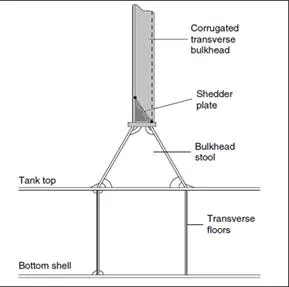
Figure 3: Elevation of a corrugated bulkhead.
The above figure shows the elevation of a corrugated bulkhead from the side. In case of bulk carriers, in order to prevent accumulation of cargo at the base of the corrugations, the lower end of the bulkheads are provided with angular plates called shredder plates, which help in shredding the dry cargo to the tank top. The bulkhead is connected to the tank top by a bulkhead stool, which is fillet welded to the tank top plate. The two forward and aft ends of the stool is to be in line with the transverse plate floors. This ensures proper stress flow from the bulkhead to the plate floors.
Figure 5: Corner plates in a transverse watertight bulkhead).
As shown above, the corners, where the bulkhead plate is welded to the side shell and the deck plate, or the tank top, separate corner plates are welded to complete the joint after welding the remaining bulkhead plate to the hull. These corner plates are provided for the following reasons:
1. Fitting the entire bulkhead panel (with the corners) would be difficult from a production point of view since every structure is first fabricated with certain amount of green material. Before final installation, the green material is removed, and structures as huge as bulkheads require repeated checks for proper dimensional adherence. Eliminating the corners from this stage would reduce the complexity of maintaining dimensional precision at the corners.
- Stress concentration occurs at corners due to discontinuity of structure. In order to prevent this, corner plates are provided with additional thickness than the adjacent bulkhead plating.


Comments are closed