The first step in designing a hull of a ship is designing its shape and form. The form of the ship’s hull is estimated by means of various form coefficients, discussed as follows:
Block Coefficient: Block coefficient is the ratio of the ship’s underwater volume to the volume of the imaginary rectangle enclosing the underwater portion of the hull. Since the length, breadth, and height of this enclosing rectangle would be the length between perpendiculars, Maximum Beam, and Draft of the ship, the block coefficient is expressed as follows:

The value of block coefficient is one for a ship with the rectangular cross-section. Hence, for a typical ship’s hull form, it would be less than one. The higher the block coefficient, the fuller is the hull form (e.g. oil tankers, bulk carriers). Finer hull-forms have lower block coefficients (e.g. container ships, warships).
Midship Coefficient: The midship coefficient is the ratio of the submerged area of the midship section to the enclosing rectangle. It is hence expressed as:

There are a number of other form coefficients like prismatic Coefficient, Volumetric Coefficient, etc. which are basically the parameters used to define the volumetric distribution of the ship’s hull along its length. Once these coefficients are arrived at, from statistical studies, the hull lines are developed.
The lines plan of a ship’s hull comprises of three views. To understand the lines plan, we first need to know what are buttocks and waterlines.
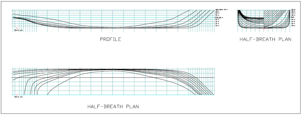
When the hull of a ship is cut into multiple sections longitudinally, that is, if you slice the ship’s hull at every two meters starting from port to starboard, you would produce longitudinal sections at every two meters. The contour of each longitudinal section is called a buttock line, and this is exactly what is represented in the profile plan, as shown below. The reference lines for the profile view are the stations (vertical grid lines, which denote the longitudinal position) and waterlines (horizontal lines, which denote vertical positions).
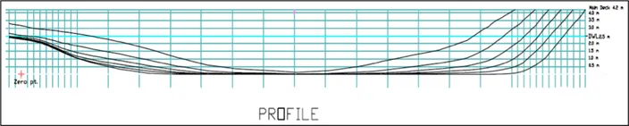
Figure 2: Buttock Lines.
If the ship’s hull is sliced along each waterline, then every waterline produces a distinct curve. Since a ship’s hull is symmetric about the centerline, a common practice prevails in which the curve is drawn on either side of the centerline, and this view is called the body plan or the half breadth plan of the ship.
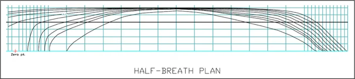
Figure 3: Half breadth plan.
Important Tip: The shape of the waterlines (in the half breadth plan) play a deciding role in the shape of the stern and the efficiency of the propeller. In the above figure, the waterlines move away from the ship’s centerline with the increase in height above baseline. That is, the innermost curve is the lowermost waterline. Take note of how the waterlines straighten at the aft as we move upward from the keel. This shows that the ship has a transom stern. So why is transom stern preferred? The answer lies in the shape of the waterlines at the stern. The longitudinal direction was taken by the waterlines at the stern ensure the flow of water at the stern in a direction almost perpendicular to the propeller disc. This ensures minimum crossflow at the propeller, therefore ensuring maximum propeller efficiency.
If the ship’s hull is sliced to form a section at every station, we obtain the body plan, as shown below. The typical practice of drawing the body plan is to denote all the half sections (due to the hull’s symmetricity). The sections forward of the midship are drawn on the right side of the center line, and all the sections from the midship to the stern are drawn on the left side.
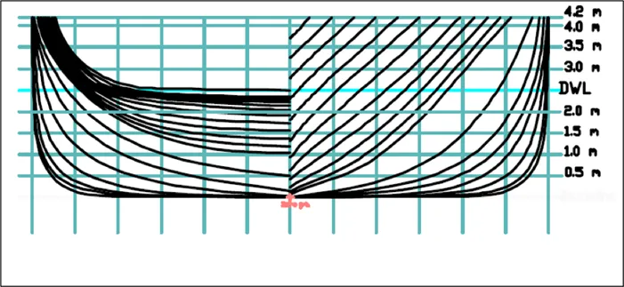
Figure 4: Body Plan.
The body plan is the most useful representation of the ship’s hull lines. The reference lines in the body plan are the buttocks (vertical grid-lines), and the waterlines (horizontal grid lines). The body plan, along with the reference lines can be self sufficiently used to develop the profile plan and half breadth plan of the ship. It is also useful in developing the sectional area curve, and bonjean curves of the ship.
The complete lines plan of a ship is arranged by placing the profile view on top, with the half breadth plan just below it, and the body plan to its right, as shown below. The lines plan provides for the foundation of developing not only the three-dimensional hull model, but also developing frame-wise structural drawings, general arrangement, and loft drawings at the shipyard.