All sea going ships are double bottomed. In such a structural arrangement, a tank top is provided above the plate and bracket floors. Bracket floors are a little different from plate floors, in as much as they are not comprised of one single plate running athwartship, but only brackets at the port and starboard ends, with struts that support the tank top with the bottom shell.
Bracket floors are mostly placed at each frame, and plate floors are generally placed at every three to four frame spaces. The space within the double bottom (that is, between the tank top, and outer bottom shell) is used up for carrying ballast, fuel oil, dirty oil, fresh water, and other consumables.
One of the most important factors in designing a double bottom of a ship, is deciding the height of the double bottom. How does a designer decide what height would be most feasible for a ship of a particular length? This is governed by the height of the keel that is required by the ship. So while estimating the scantlings of a ship, the designer first calculates (using the rules specified by the authorised Classification Society) the height of the centre girder, which must always be housed within the double bottom. Hence, this factor now decides the double bottom height.
Double bottom heights often increase in ways of engine rooms, as they need to take up higher stresses due to heavy machinery in those regions. In engine room region, all the frames are provided with plate floors, and no bracket floors are used. However, there is another factor a designer must take care of, while providing an increased double bottom height in high stress regions. The height must not be increased abruptly, therefore resulting in a discontinuity, which would lead to concentration of stresses, and eventually a structural failure. So the increase in height should be gradually tapered up and down. The taper should start a few frames forward of the engine room bulkhead, and continue up to a three or four frames aft of the engine room to allow proper stress flow or structural continuity.
The intricacy in design of a bottom structure begins after one has understood the above concepts. We have seen two separate categorisations of double bottoms. First dealt with the type of stiffening used, and the second dealt with single and double bottoms. When a ship’s bottom structure is designed, both the categories are mixed together to obtain the final structure. Most budding naval architects initially find this part confusing, which is why, let us first list down the four types of possible bottom structures:
· Transversely Framed, Single Bottom
· Transversely Framed, Double Bottom
· Longitudinally Framed, Single Bottom
· Longitudinally Framed, Double Bottom
Out of these four types, three are used, and one is not. While it is easy for experienced designers to point out that one type, it may not be easy for everyone. Because there is an underlying concept to it, which we shall understand now.
Why is longitudinal framing used when we could easily have provided transverse framing in longer ships too? The answer lies in the fact that ships longer than 120 meter are subjected to high global longitudinal bending stresses like hogging and sagging in different load conditions, unlike smaller ships. So if longer ships would be stiffened transversely, the transverse stiffeners would have no role in taking up the longitudinal bending stresses of the hull girder, and therefore lead to more chances of failure. Hence, stiffeners are aligned longitudinally in longer ships.
It should be very clear now, that since longer ships have longitudinal stiffening, and since they are also designed to carry higher amount of cargo, a double bottom is necessary. Hence, longitudinally framed single bottom structures (3rd in the above list) do not exist.
Since we are now done with the basics of a bottom structure, it would be easy to visualise each type henceforth.
TYPE 1: SINGLE BOTTOM, TRANSVERSELY FRAMED (Refer to the Figure 1)
· The plate floors act as transverse stiffeners, and their spans are reduced by the use of intercostal side girders that run longitudinally.
· Most single bottom ships are provided with bar keel that extends along the length of the ship up to a certain waterline at the stem. The bar is slightly protruded outside the outer bottom shell.
· The outer bottom shell plating just adjacent to the bar keel is called Garboard strake, and its thickness is more than the thickness of the remaining bottom shell.
· All the plate floors are flanged at their tops, so as to increase their bending strength.
· Manholes are provided in the plate floors for crew access. These holes are flange too, so as to reduce stress concentration.
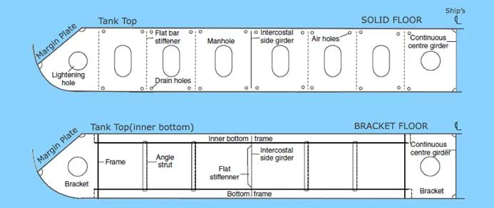
TYPE 2: DOUBLE BOTTOM, TRANSVERSELY FRAMED (Refer to the Figure 2)
· This is used in ships of length less than 120 meters. (See how the length factor dominates over the type of framing used)
· The bracket floors form the transverse stiffeners at every frame, and plate floors are used at every 3 to 4 frame spaces, or 1.8 meters intervals.
· Similar to the single bottom, to reduce the span of the plates, intercostal side girders of keelsons are used that run longitudinally. An important thing to note, is that the side girders are continuous members, that is, where there is an intersection between a plate floor and a side girder, the plate floor is cut and welded on both the sides of the girder, and not the other way round. Why? Remember, we needed to reduce the span of the plate floors, hence the girders will act as supporting members to the plate floors.
· Flat plate keels are used in these structures. The keel plating thickness is a very important decision maker in the strength of the ship. This is to be calculated from the formula dedicated to this purpose, provided by the relevant classification society.
· Intercostal girders or side girders, and plate floors will have lightening holes at regular intervals to reduce the structural weight, and will have manholes (flanged) to provide access.
· Drain holes will be provided in the plate floors to help drainage of liquids. Plate floors are further stiffened by flat bar stiffeners (see image below), and bracket floors, by angle struts to prevent warping.
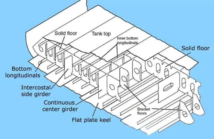
Figure 2: Double Bottom, Transversely Framed (Perspective view and Transverse view)
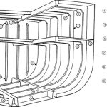
TYPE 3: DOUBLE BOTTOM, LONGITUDINALLY FRAMED (Refer to image)
· The prime stiffening members are longitudinally running bulb sections or angle sections. The stiffeners on the bottom plating are called outer bottom longitudinals, and those that stiffen the tank top plating are called tank top longitudinals.
· The span of each longitudinal is equal to three of four frame spaces. That is, at each three or four frame, there would be a plate floor to support the longitudinal. A bracker floor is places at almost every frame, but it does not support the longitudinals.
· Intercostal girders are used, as usual, to reduce the span of the plate floors.
· If you notice carefully, the longitudinals run across plate floors through holes called scallops. So in a frame, where it is required to support the span of a longitudinal using a plate floor, the longitudinal is welded with a small plate to the plate floor, therefore rendering the scallop as a support end.
· In bracket floors, tank top and bottom shell longitudinals are supported to each other by means of angle struts.
· In plate floors, the longitudinals of the tank top and bottom shell are supported to each other by flat bar stiffeners, to restrict bending, torsion, and buckling.
· As usual, drain holes are used for fluid drainage and air holes are used for passage of air. Note their positions in the images, to visualise the exact layout.
· Margin plates are used in some designs, to lead the flow of waste fluids (bilge) towards the bilge wells on either sides of the ship.
· A continuous centre girders runs through the length of the ship, supporting the entire bottom structure, the keel plate, and the garboard strake.
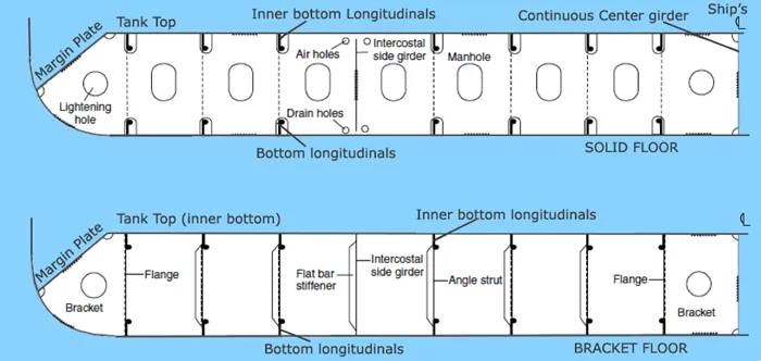
Figure 3: Longitudinally Framed Double Bottom (Perspective View and Transverse View)
In modern analyses of bottom structure of ships, designers take a lot of care for various modes of failure. A disastrous mode of failure other than bending, is buckling, which a bottom structure can be often subjected to. For example, consider a ship to be hogging. The outer bottom shell undergoes a compression that leads to buckling of the bottom plate, and associated structure. Torsion can also be a mode of failure in cases of container ships.
So, as a ship designer, when one analyses the feasibility of a bottom structure, it is important to test for all possible modes and types of failure. Because, for example, if a designer certifies a bottom structure only on the basis of bending stress, without taking into consideration buckling or torsion. What could happen? In a situation, when buckling occurs, the structure might fail due to buckling (if it’s buckling strength is lesser than its bending strength), even when the bending stresses have not reached the failure limits!
Hence, the principle design criteria must be decided base on all possible modes of failure, at various load cases, analysed by efficient and certified FEM tools, so as to attain a safe and economical factor of safety for the structure, from all possibilities of failures at sea.

Comments are closed