The power required to propel a ship is proportional to its speed times the resistance to its movement. The ability to predict resistance is therefore the essential ingredient in predicting the propulsive power to be required by a prospective ship. For many years hydrodynamic researchers have sought a method for calculating this resistance from first principles, but so far they have not produced a generally practicable method. Estimates can be made based on experience with existing ships or standard models, but the favoured way of making a prediction during design is to test a model of the proposed ship.
Model testing consists of towing a precisely made model of the hull at a precisely controlled speed, in calm water, while measuring the force required to tow it. The essential link between model and ship is obtained by operating the model at the same Froude number as the ship. This number, named after the English naval architect William Froude, is a dimensionless ratio given as V/(gL)0.5, in which V is the speed, gthe acceleration of gravity, and L the waterline length. At this common reference point the wave patterns developed by the ship and by the model are the same, and residuary resistances per ton of displacement also are the same. Unfortunately, equality of Froude numbers means a gross inequality in Reynolds numbers, causing a serious mismatch between the frictional resistances of model and ship. The technique of scaling from model to ship therefore must follow a somewhat devious path whose principal steps are as follows: (1) Total resistance of the model is measured. (2) Frictional resistance of the model is calculated, using data and techniques published by the International Towing Tank Conference. (3) Residuary resistance for the model is found by subtracting the frictional component from the total. (4) Residuary resistance for the ship is taken to be the same, per ton of displacement, as for the model. (5) Frictional resistance for the ship is calculated. (6) Total resistance is obtained by adding the resistance components found in steps 4 and 5.
Ship manoeuvring and directional control
A ship is said to be directionally stable if a deviation from a set course increases only while an external force or moment is acting to cause the deviation. On the other hand, it is said to be unstable if a course deviation begins or continues even in the absence of an external cause. A directionally unstable ship is easy to maneuver, while a stable ship requires less energy expenditure by its steering gear in maintaining a set course. A compromise between extremes is therefore desirable. In a rough sense, directional stability or instability can be determined by examination of the ship’s underwater profile. If the area of the hull and its appendages is concentrated toward the aft end, then the ship is likely to be directionally stable.
Neither stability nor instability obviates the need for devices to maintain a course or to change it on command. The near-universal gear for such directional control is a rudder (or rudders) fitted to the stern and activated by an electrohydraulic steering engine mounted within the hull just above. The rudder is an appendage that has a cross section much like an airfoil and that develops lift when it is turned to produce a nonzero angle of attack relative to the water. The lift produces a turning moment around a point that is located somewhere along the mid-length of the hull.
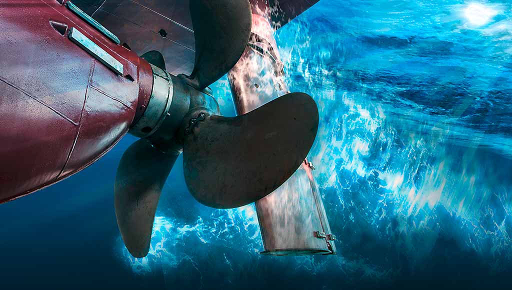
For a given angle of attack, rudder lift is proportional to the square of the water velocity relative to the rudder. Therefore, the preferred position for a rudder is within the high-velocity wash generated by a propeller. In the case of a multi-propeller ship, multiple rudders may be fitted (one behind each propeller) in order to take advantage of high water velocity. In addition, a ship that must maneuver well while backing is often fitted with a pair of “flanking rudders” for each propeller. These are positioned forward of the propeller, one on each side of the shaft.
Maneuvering at very low speeds is a special problem, since low water velocity means insufficient lift developed by the rudder. If the rudder is positioned directly behind a propeller, then a few seconds of high propeller speed can develop lift sufficient to push the stern sideways before generating significant forward motion of the hull. Pushing the stern sideways is tantamount to changing the direction of the hull, but this expedient is often not sufficient for low-speed maneuvering. For this reason, many ships are fitted with a “bow thruster,” a propeller mounted in a transverse tunnel near the bow. This thruster can push the bow sideways without producing forward motion. If a similar thruster is fitted near the stern, a ship can be propelled sideways—or even rotated in place, if the two thrusters act in opposite directions.


Comments are closed